PC66
LPSPL
Mark
detection
range +
(lower three
digits)
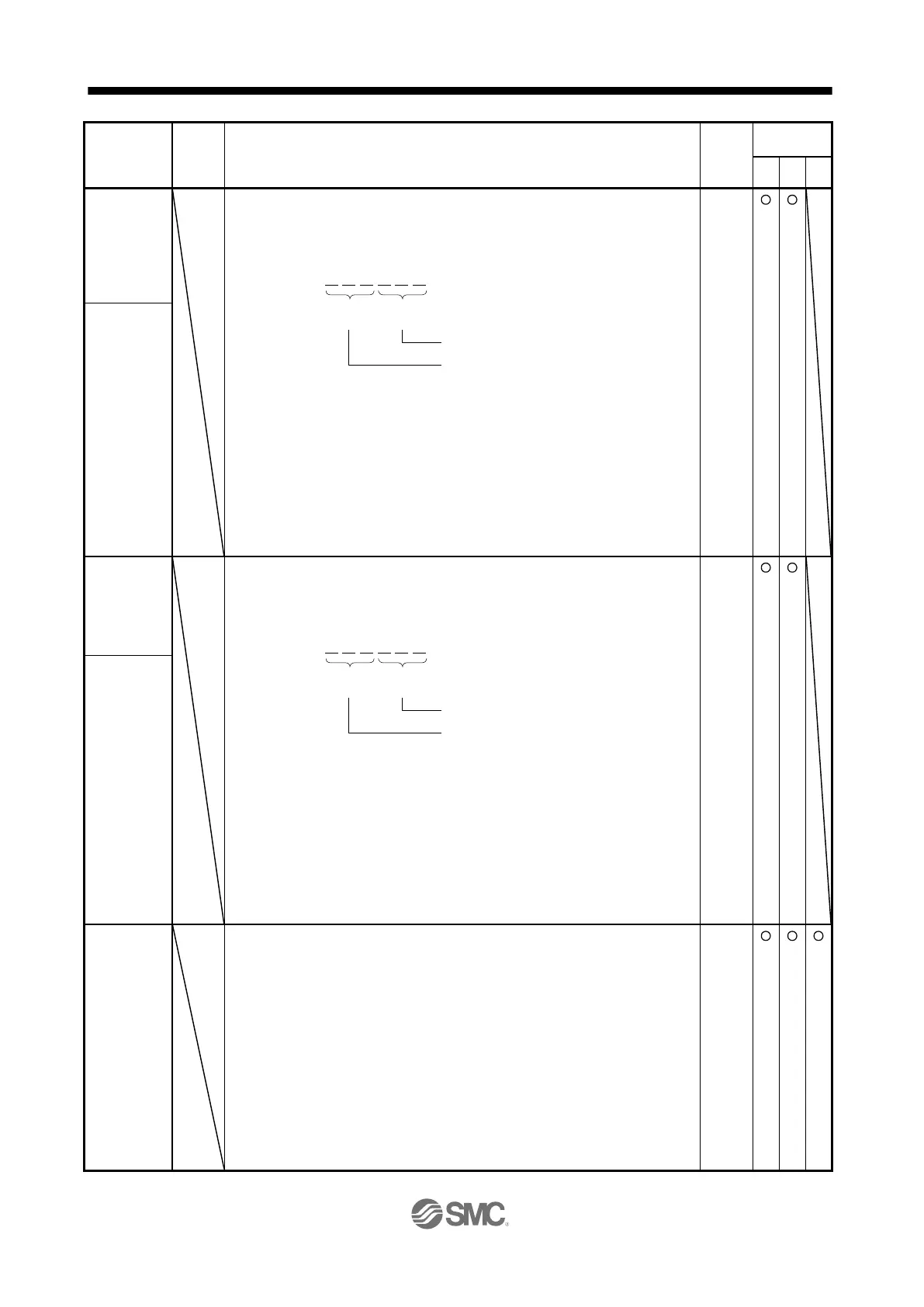
Set the upper limit of the mark detection.
Upper and lower are a set.
When the roll feed display is enabled, set this value with the travel distance from the
starting position.
Setting address:
The unit will be changed to 10
STM
[μm], 10
(STM-4)
[inch], 10
-3
[degree], or [pulse] with
the setting of [Pr. PT01].
Set a same sign for [Pr. PC66] and [Pr. PC67]. A different sign will be recognized as
minus sign data.
When changing the direction to address decreasing, change it from the - side of the
mark detection ([Pr. PC68] and [Pr. PC69]). An incorrect order of the setting will
trigger [AL. 37]. Therefore, cycling power may be required after [Pr. PC66] to [Pr.
PC69] are all set.
Setting range: -999 to 999
0
Refer
to
Functio
n
column
for unit.
PC67
LPSPH
Mark
detection
range +
(upper three
digits)
PC68
LPSNL
Mark
detection
range - (lower
three digits)
Set the lower limit of the mark detection.
Upper and lower are a set.
When the roll feed display is enabled, set this value with the travel distance from the
starting position.
Setting address:
The unit will be changed to 10
STM
[μm], 10
(STM-4)
[inch], 10
-3
[degree], or [pulse] with
the setting of [Pr. PT01].
Set a same sign for [Pr. PC68] and [Pr. PC69]. A different sign will be recognized as
minus sign data.
When changing the direction to address increasing, change it from the + side of the
mark detection ([Pr. PC66] and [Pr. PC67]). An incorrect order of the setting will
trigger [AL. 37]. Therefore, cycling power may be required after [Pr. PC66] to [Pr.
PC69] are all set.
Setting range: -999 to 999
0
Refer
to
Functio
n
column
for unit.
PC69
LPSNH
Mark
detection
range -
(upper three
digits)
PC73
ERW
Error
excessive
warning level
Set an error excessive warning level.
To enable the parameter, set "[AL. 9B Error excessive warning] selection" to
"Enabled (1 _ _ _)" in [Pr. PC60].
The setting unit can be changed with "Error excessive alarm/error excessive warning
level unit selection" in [Pr. PC24].
Set this per rev. for rotary servo motors and direct drive motors. When "0" is set, 1
rev will be applied. Setting over 200 rev will be clamped to 200 rev.
When an error reaches the set value, [AL. 9B Error excessive warning] will occur.
When the error decreases lower than the set value, the warning will be canceled
automatically. The minimum pulse width of the warning signal is 100 [ms].
Set as follows: [Pr. PC73 Error excessive warning level] < [Pr. PC43 Error excessive
alarm level] When you set as [Pr. PC73 Error excessive warning level] ≥ [Pr. PC43
Error excessive alarm level], [AL. 52 Error excessive] will occur earlier than the
warning.
Setting range: 0 to 1000
Upper
3 digits
Lower 3
digits
[Pr. PC66]
[Pr. PC67]
Upper
3 digits
Lower
3 digits
[Pr. PC68]
[Pr. PC69]

 Loading...