Arm
®
CoreLink™ GIC-600AE Generic Interrupt Controller
Technical Reference Manual
Document ID: 101206_0003_04_en
Issue: 04
Functional Safety
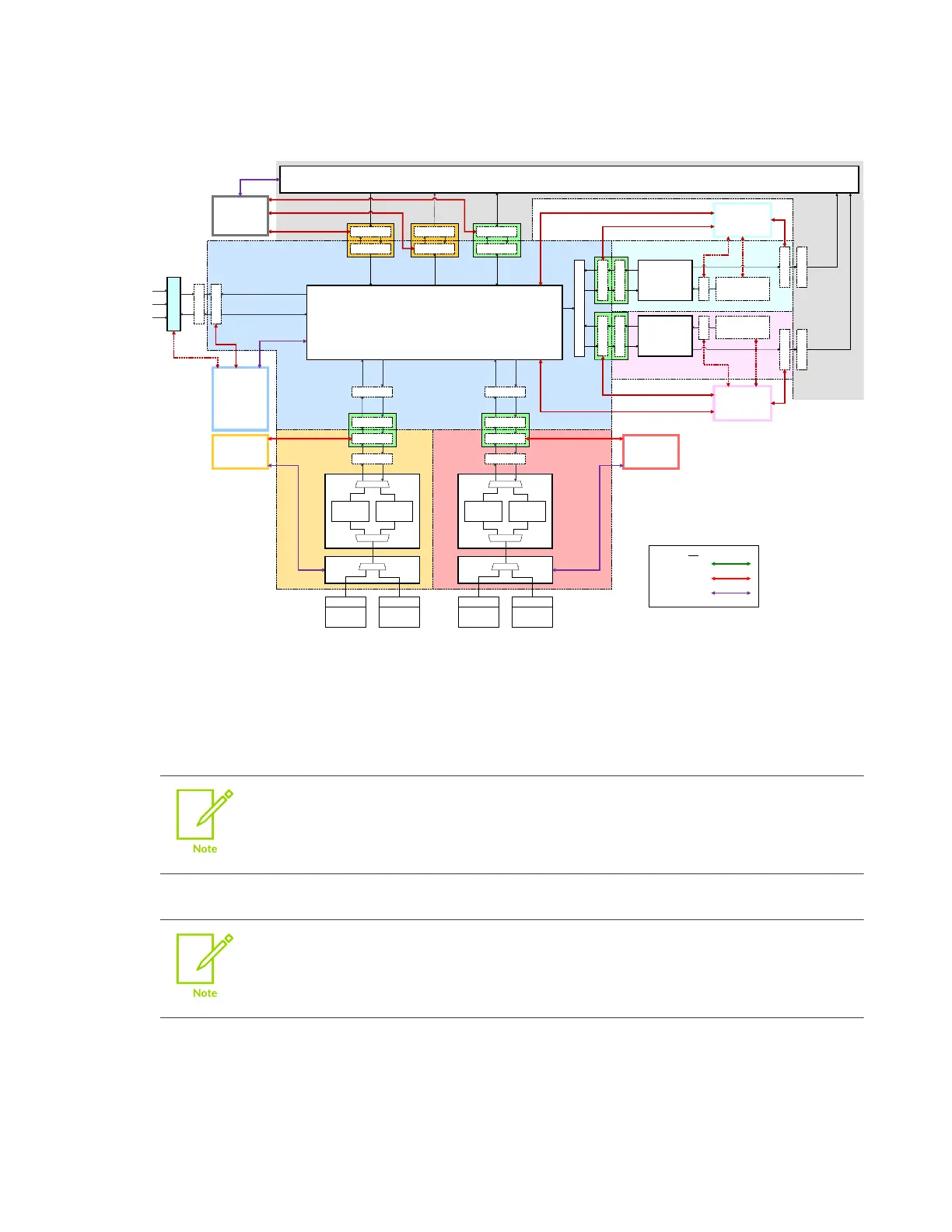
Figure 6-13: GIC topology with multiple power domains
This could also be
controlled by another
domain if the SPI Collator
is located there.
Key
Clock Q-Channel
Power Q-Channel
P-Channel
ACE-Lite manager
ACE-Lite
subordinate
(Config)
This example power domain hook-up has the following power domain relationships:
•
Core before cluster
•
Cluster before GICD
•
ITS before GICD
Possible scenarios also relate to making the ITS quiescent while the I/O domain
is on.
•
GICD before interconnect
It is also beneficial to control the interconnect before the GICD. This implies
different control on the bridges, either from the other side, or independent/
combined if there is no fixed relationship.
In Figure 6-12: GIC topology with multiple clock domains on page 233 and Figure 6-13: GIC
topology with multiple power domains on page 234, the Q-Channel connections are made by
the GIC rendering engine. The GIC uses a Q-Channel for power control in all cases except for
cross/remote chip power control, which uses a P-Channel port on the Distributor.
Copyright © 2018–2020, 2022 Arm Limited (or its affiliates). All rights reserved.
Non-Confidential
Page 234 of 268