EasyManua.ls Logo

Austro Engine E4 Series - Page 162

Default Icon
658 pages
Print Icon
To Next Page IconTo Next Page
To Previous Page IconTo Previous Page
Loading...
E4 Series
Maintenance Manual
Standard
Procedures
Page 218
E4.08.04
Rev.29
70 - Maintenance Procedures
01-Jul-2020
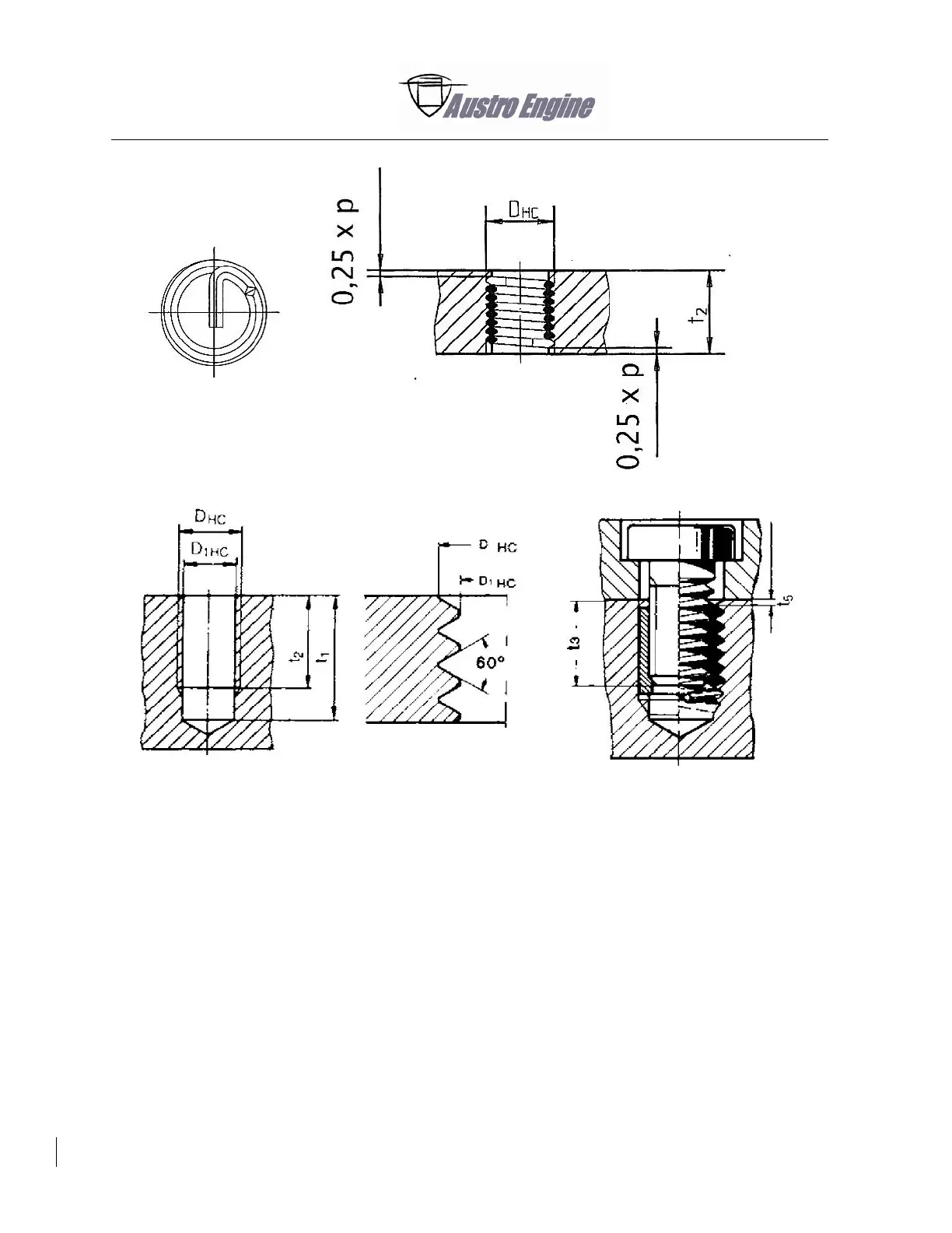
Fig. 70 - 17 Installation drawing for threaded inserts
D = Nominal thread diameter
P = Thread pitch
D
HC
= Holding thread outside diameter
D
1HC
= Core hole thread diameter
t
1
= Minimum depth of core hole
t
2
= Thread depth
t
3
= Maximum screw-in depth with tang not broken off
t
5
= Distance of thread insert from the separating surface.

Table of Contents

Other manuals for Austro Engine E4 Series

Related product manuals