EasyManuals Logo

Austro Engine E4 Series User Manual

Default Icon
658 pages
To Next Page IconTo Next Page
To Previous Page IconTo Previous Page
Page #358 background imageLoading...
Page #358 background image
E4 Series
Maintenance Manual
Engine Control
System
Page 208
E4.08.04
Rev.29
76 - Maintenance Procedures
01-Jul-2020
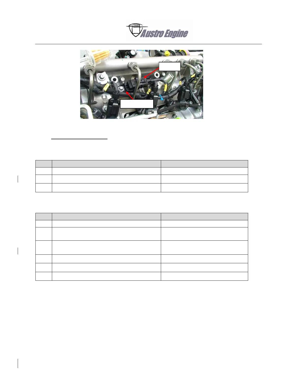
Fig. 76 - 12 Camshaft Sensor CAS1
6. Camshaft Sensor CAS2
A. Remove the Camshaft Sensor CAS2
Detail Steps/Work Items
Key Items/References
(1)
Pull down the electrical connector CAS2.
(2)
Remove the locking screw from the sensor.
Refer to Fig. 76 - 13 or Fig. 76 - 14.
(3)
Pull out the camshaft sensor.
B. Install the Camshaft Sensor CAS2
Detail Steps/Work Items
Key Items/References
(1)
Lubricate the new O-Ring with engine oil.
Refer to the Consumable list.
(2)
Push the sensor into the sensor housing.
Make sure the O-Ring is in correct
position.
(3)
Tighten the locking screw from the camshaft
sensor.
Torque 12 Nm.
Refer to Fig. 76 - 13 or Fig. 76 - 14.
(4)
Make sure the sensor is in correct position.
(5)
Connect the electrical connector CAS2.
(6)
Do an engine ground run.
Refer to Section 71-00-01.
Locking screw
CAS1

Table of Contents

Other manuals for Austro Engine E4 Series

Questions and Answers:

Question and Answer IconNeed help?

Do you have a question about the Austro Engine E4 Series and is the answer not in the manual?

Austro Engine E4 Series Specifications

General IconGeneral
BrandAustro Engine
ModelE4 Series
CategoryEngine
LanguageEnglish

Related product manuals