24-00-00 Electrical Power
1. Electrical System Description
The Electrical System consists of the following major components:
– Starter (refer to Chapter 80)
– Generator
– GPC – Glow Plug Control Unit (refer to Chapter 80)
– EECU – Electronic Engine Control Unit (refer to Chapter 76)
– Sensors & Actuators (refer to Chapter 76)
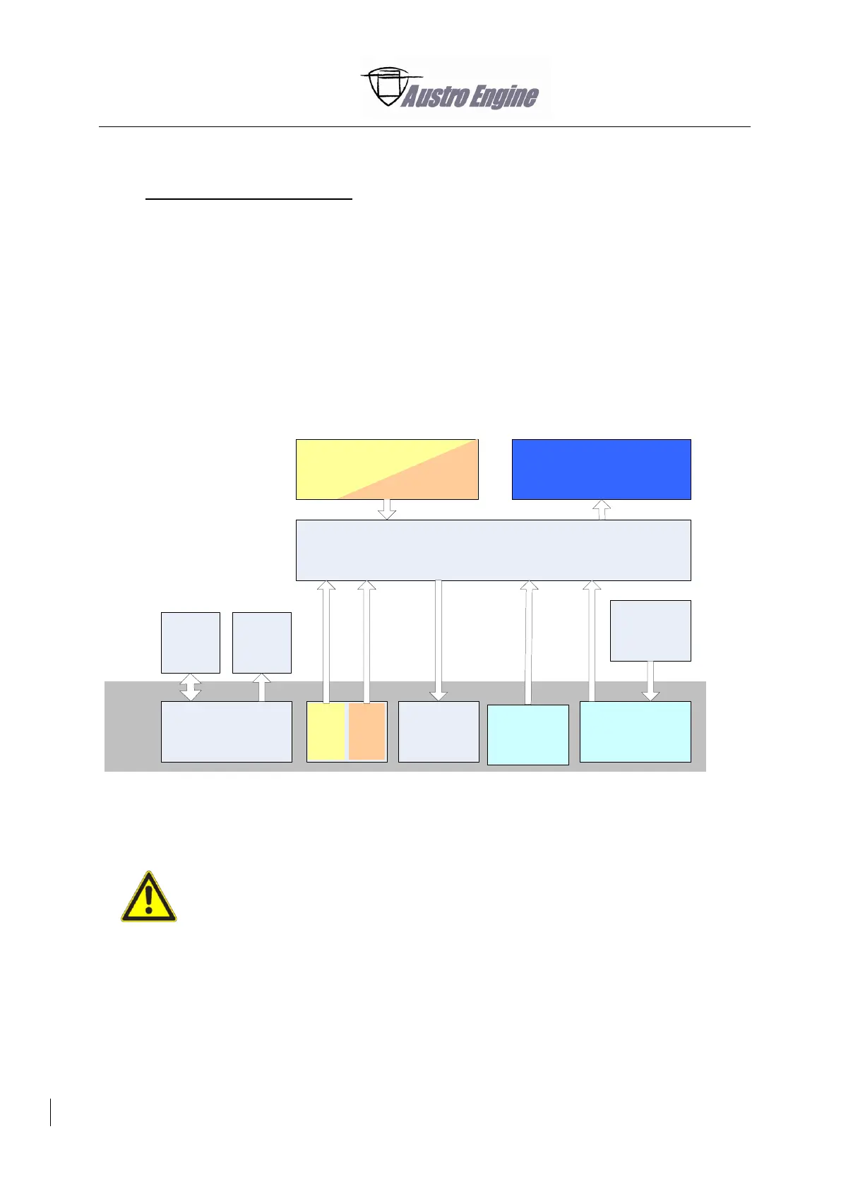
The Electric Engine Control System (EECS) Block Diagram shows the connection between the EECS
components and displays the Interface from the Airframe to the EECS of the E4 engine.
When you work on the electrical system, disconnect the power supply as
follows:
the negative pole of the battery
the positive pole of the battery
For connection, do the opposite procedure.
EECU
Actuators
Glow
Plug
Control
Starter
Generator
A/C
EECS
Engine
Monitoring
System
Control
signals
A/C PowerA/C Interface
Engine Sensors
Power
Lever
Fig. 24 - 1 EECS Block Diagram