Home
Austro Engine
Engine
E4 Series
Austro Engine E4 Series User Manual
5
of 1
of 1 rating
658 pages
Give review
Manual
Specs
To Next Page
To Next Page
To Previous Page
To Previous Page
Loading...
E4 Series
Maintenance Manual
Engine Control
System
E4.08.04
Rev.29
Page
205
76
- Maintenance Procedures
01-Jul-
2020
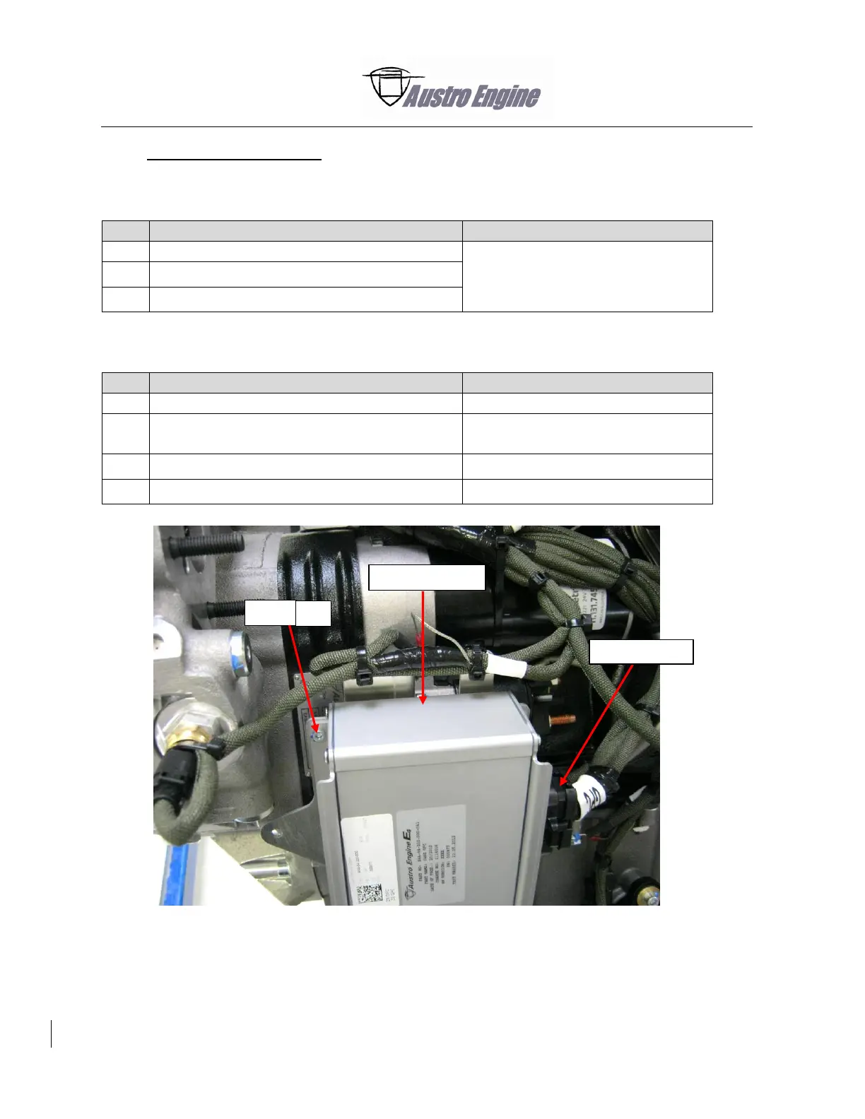
3.
Glow Plug Control
(GPC)
A.
Remove the Glow Plu
g Control
Detail Steps/Work I
tems
Key Items/Referenc
es
(1)
Remove the GPC
connector.
Refer to Fig. 76 -
10
.
(2)
Remove the four scre
ws from the G
PC
.
(3)
Remove the G
PC
.
B.
Install the Glow
Plug Control
Detail Steps/Work I
tems
Key Items/Referenc
es
(1)
Put the G
PC
in position.
Refer to Fig. 76 -
10
.
(2)
Tighten the nuts o
n the G
PC
.
Use only new stop nuts
.
Torque 4 Nm.
(3)
Connect the G
PC
co
nnector.
Refer to Fig. 76 -
10
.
(4)
Do
an engine gro
und run.
Refer to Sectio
n 71-
00
-
01.
Fig. 76 -
10
Glow Pl
ug Control
Plug connect
ion
Glow P
lug
Control
Screw
4x
354
356
Table of Contents
Table of Contents
7
Introduction
9
General
9
Warning, Cautions and Notes
10
Manual Configuration
10
Chapter Configuration
11
Page Numbering System
11
Figures
11
Revisions
12
List of Revisions
13
List of Included Temporary Revisions
19
List of Service Bulletins Included as Maintenance Procedures
21
Abbreviations
22
General
22
Engine Harness
23
Conversion Factors
24
Conversion Table of Given Torque Values
24
Conversion Table of Given Pressure Values
25
Engine Power Conversions
25
Consumable List
26
General Description of the Engine
27
Transport and Packaging
39
General
39
Packaging
39
Transport
43
Protective Covers
44
Storage and Preservation
45
Storage of a Received Engine
45
Preservation of an Installed Engine
45
Engine Depreservation
47
Engine Storage
48
Return Parts Shipping Instructions
49
Time Limits and Maintenance Check
63
General
63
Words for Special Meanings
64
Claimable Exceed of Maintenance Actions
66
Component Time Limits and Maintenance Requirements
67
Component Time Limits
68
Component Maintenance Requirements
69
Engine Time between Overhaul
70
Scheduled Maintenance Checks
71
Unscheduled Maintenance Checks
76
Performance Deterioration
76
Violation of Temperature Limits
76
Sudden Stoppage Inspection
76
Propeller Strike
76
Lightning Strike
76
High Engine Oil Consumption Inspection
77
Engine Oil System Contaminated
77
Engine Oil Pressure Loss Inspection
77
Inability to Start the Engine
77
Engine over Speed
77
Servicing
82
Engine Oil Servicing
83
Complete a Check of the Oil Level
83
Do a Check of the Gearbox Oil Level
84
Engine Coolant Servicing
84
Electrical Power
89
Electrical System Description
89
Electrical System Installation
90
Alternator
90
Alternator-Regulator Adjustment E4A-91-200-000
91
Paralleling for Twin Engine System E4A-91-200-000
91
Troubleshooting Information
93
General
93
Alternator E4A-91-000-000
95
General
95
Maintenance Procedures
95
Remove the Alternator
95
Install the Alternator
96
Acceptance Criteria for Alternator Bench Tests
98
Inspection of Alternator E4A-91-000-000 and the Carbon Brushes
98
Special Tools
98
Remove the Brush Holder Assembly
98
Visually Examine the Alternator Housing and Pulley
99
Examine the Contact Ring and Brushes
100
Disassemble the Brush Holder Assembly E4A-91-300-000
101
Measure the Length of Carbon Brushes
104
Complete the Brush Holder
104
Install the Brush Holder
106
Functional Check
109
Alternator E4A-91-400-000
116
General
116
Maintenance Procedures
116
Remove the Alternator
116
Install the Alternator
117
Acceptance Criteria for Alternator Bench Tests
120
Inspection of Alternator E4A-91-400-000 and Carbon Brushes
120
Special Tools
120
Remove the Brush the Holder Assembly
120
Visually Examine the Alternator Housing and Pulley
123
Examine the Contact Ring and Brushes
124
Examine the ASSY Brush Holder E4A-91-410-000
125
Measure the Length of Carbon Brushes
125
Install the Brush Holder
126
Functional Check
130
Alternator-Regulator E4A-91-100-000
135
General
135
Adjust the Voltage Regulation E4A-91-100-000
136
Adjust the Alternator Balancing E4A-91-100-000 (Only for Twin-Engine Applications)
136
Replace Alternator-Regulator E4A-91-100-000
136
Standard Procedures
141
General
141
Safetying Methods
141
Standard Torque Values
141
Troubleshooting Information
143
General
143
Safety Wiring
145
General
145
Special Tools
145
Basic Rules
145
Safety Wiring Methods
146
Single Wire Locking
147
Double Wire Locking
148
Examples of Safety Wiring
153
Torque Procedure
157
Installation of Helical Threaded Inserts
161
General
161
Special Tools
164
Install the Threaded Insert
164
Examine the Threaded Insert for Correct Installation
167
Remove the Threaded Inserts
167
Safety the Rotating Threaded Inserts
168
Power Plant
173
General
173
Description
173
Electrical Harness
173
Engine Harness Routing Overview
177
Engine Harness Routing General Instructions
183
Troubleshooting Information
185
General
185
Engine Ground Run
187
General
187
Engine Ground Run Instructions
188
Electrical Harness
190
General
190
Maintenance Procedures
190
Examine the Engine Wiring Harness
190
Examine the Sensors / Actuators
193
Install the Engine Wiring Harness for E4A-90-000-000
194
Install the Engine Wiring Harness E4A-95-000-000 and E4B-95-000-000
213
Engine Fuel and Control
307
General
307
System Description
307
Troubleshooting Information
311
General
311
Engine Fuel Supply
313
General
313
Special Tools
313
Injectors
313
Remove the Injectors
313
Install the Injectors
314
Fuel Return Line
320
Remove the Fuel Return Line
320
Install the Fuel Return Line
320
High Pressure Pump (HPP)
324
Remove the High Pressure Pump (HPP)
324
Install the High Pressure Pump (HPP)
327
Remove the Spur Gear from High Pressure Pump
328
Install the Spur Gear from High Pressure Pump
329
Engine Fuel Control
330
General
330
Low Fuel Pressure Sensor (FPS)
330
Remove the Fuel Pressure Sensor
330
Install the Fuel Pressure Sensor
330
Fuel Rail
331
Remove the Fuel Rail
331
Install the Fuel Rail
331
Engine Control System
337
General
337
System Description/Operation
337
Engine Electronic Control Unit (EECU)
337
Troubleshooting Information
349
General
349
Engine Control
351
General
351
Engine Electronic Control Unit (EECU)
351
Complete an EECU Software Update
351
Examine the EECU Fault Log
354
Glow Plug Control
355
Remove the Glow Plug Control
355
Install the Glow Plug Control
355
Crankshaft Sensor
356
Remove the Crankshaft Sensor
356
Install the Crankshaft Sensor
356
Camshaft Sensor CAS 2
358
Engine Indicating
365
General
365
System Description/Operation
365
Troubleshooting Information
367
General
367
Engine Exhaust System
373
General
373
System Description/Operation
373
Troubleshooting Information
375
General
375
Engine Exhaust
377
General
377
Exhaust Manifold
377
Remove the Exhaust Manifold
377
Install the Exhaust Manifold
378
Exhaust Manifold Gasket Exchange
381
Engine Oil System
387
General
387
System Description/Operation
387
Troubleshooting Information
389
General
389
Oil Storage
391
General
391
Special Tools
391
Oil Sump
391
Remove the Oil Sump
391
Install the Oil Sump
392
Oil Supply
396
General
396
Oil Filter Housing
396
Remove the Oil Filter Housing
396
Install the Oil Filter Housing
396
Oil Filter
396
Remove the Oil Filter
396
Install the Oil Filter
397
Oil Filter Housing Drain Line
400
Remove the Oil Filter Housing Drain Line
400
Install the Oil Filter Housing Drain Line
401
Engine Oil
403
Drain the Engine Oil
403
Fill the Engine Oil
403
Oil Separator
405
Remove the Oil Separator
405
Install the Oil Separator
405
Remove the Oil Separator By-Pass Valve
406
Install the Oil Separator By-Pass Valve
406
Oil Separator Return Line
408
Remove the Oil Separator Return Line
408
Install the Oil Separator Return Line
408
Turbocharger Oil Supply Line
412
Remove the Turbocharger Oil Supply Line
412
Install the Turbocharger Oil Supply Line
412
Turbocharger Oil Return Line
416
Remove the Turbocharger Oil Return Line
416
Install the Turbocharger Oil Return Line
416
Remove and Disassemble the Banjo Bolt/Adapter Assembly
420
Install and Assemble the Banjo Bolt/Adapter Assembly
420
Oil System Sensors
424
General
424
Oil Level Sensor
424
Remove the Oil Level Sensor
424
Install the Oil Level Sensor
424
Oil Pressure Sensor
426
Remove the Oil Pressure Sensor
426
Install the Oil Pressure Sensor
426
Starting
432
General
433
System Description
433
Electrical Starter
433
Glow Plug Control Unit
433
Troubleshooting Information
435
General
435
Cranking
437
General
437
Starter
437
Remove the Starter
437
Install the Starter
438
Glow System
440
Examine the Glow Plug Control Unit (GPC)
440
Remove the Glow Plugs
441
Install the Glow Plugs
441
System Description
447
General
447
Charged Air System
447
Turbocharger
447
Components of the Aircraft
450
Part of the Engine
450
Troubleshooting Information
451
General
451
Turbocharger
451
General
453
Special Tools
453
Turbocharger
453
Remove the Turbocharger
454
Install the Turbocharger
454
Boost Pressure Actuator (BPA)
456
Remove the BPA
456
Install the BPA
456
Wastegate Controller
460
Remove the Wastegate Controller
460
Install and Adjust the Wastegate Controller
462
Examine the Wastegate Controller Adjustment
466
Install the Wastegate Controller Conrod Fail-Safe Bridge
468
Reciprocating Engine
479
System Description/Operation
479
Governor
485
Troubleshooting Information
487
General
487
Reciprocating Engine - Front Section
489
General
489
Special Tools
489
Injector Cover
489
Remove the Injector Cover
489
Install the Injector Cover
490
Gearbox
495
Remove the Gearbox
495
Install the Gearbox
496
Remove the Optional Gearbox Oil Cooler
501
Install the Optional Gearbox Oil Cooler
501
Remove and Examine the Magnetic Drain Plug
503
Install the Magnetic Drain Pug
504
Remove the Gearbox Oil Filter
506
Install the Gearbox Oil Filter
507
Remove the Gearbox Temperature Sensor
508
Install the Gearbox Temperature Sensor
508
Gearbox Oil
510
(A) Drain the Gearbox Oil
510
(B) Fill the Gearbox Oil
510
Two-Mass-Flywheel
511
Remove the Two-Mass-Flywheel
511
Install the Two-Mass Flywheel
512
Examine the Hub
517
Examine the Two-Mass Flywheel
519
Replace the Two-Mass Flywheel
521
Replace the Two-Mass Flywheel
537
Clean the Two-Mass Flywheel
538
Mark the Two-Mass Flywheel after Inspection
540
Assembly the Two-Mass Flywheel
541
Pack and Ship the Two-Mass Flywheel
541
Engine Carrier Mounting Gearbox
542
Repair the Damaged Threads
542
Gearbox Shaft Seal
545
Remove the Gearbox Shaft Seal
545
Install the Gearbox Shaft Seal
546
Reciprocating Engine - Power Section
548
Crankshaft Cover
548
Remove the Crankshaft Cover
548
Install the Crankshaft Cover
549
Reciprocating Engine - Cylinder Section
551
Intake Air System
551
Remove the Intake Air Manifold
551
Install the Intake Air Manifold
552
Boost Pressure Sensor (BPS)
559
Remove the BPS
559
Install the BPS
559
Intake Air Temperature Sensor (IAT)
561
Remove the IAT Sensor
561
Install the IAT Sensor
561
Cylinder Head
562
Remove the Cylinder Head
563
(A) Remove the Parts Attached to the Cylinder Head
565
(B) Remove the Cylinder Head Cover
566
(C) Remove the Camshaft Sensor Housing for CAS 2
567
(D) Remove the Rear Cylinder Head Cover
569
(E) Remove the Front Cylinder Head Cover
570
(F) Remove the Chain Tensioner
571
(G) Remove the Chain Gear
571
(H) Remove the Camshafts
572
(I) Remove the EGR (Exhaust Gas Recirculation) Closing Cover Top
573
(J) Remove the EGR (Exhaust Gas Recirculation) Closing Cover Bottom
573
(K) Remove the Cylinder Head Sub-Assembly from the Crankcase
574
Install the Cylinder Head
576
(A) Install the Cylinder Head Sub-Assembly on the Crankcase
576
(B) Install the EGR Closing Cover Top
580
(C) Install the EGR Closing Cover Bottom
580
(D) Install the Camshafts
581
(E) Install the Chain Gear
585
(F) Install the Chain Tensioner
586
(G) Install the Front Cylinder Head Cover
587
(H) Install the Rear Cylinder Head Cover
588
(I) Install the Camshaft Sensor Housing for CAS 2
589
(J) Install the Cylinder Head Cover
593
(K) Install the Parts Attached to the Cylinder Head
596
Reciprocating Engine - Rear Section
598
V-Ribbed Belt
598
Remove the V-Ribbed Belt
598
Install the V-Ribbed Belt
598
Belt Tensioner
600
Remove the Belt Tensioner
600
Install the Belt Tensioner
600
Belt Tensioner - Roller
601
Remove the Belt Tensioner - Roller
601
Install the Belt Tensioner - Roller
601
Timing Chain
602
Timing Chain Check
602
(A) Prepare for Timing Chain Check
602
(B) Timing Chain Measuring Tool (TCMT)
603
(C) Complete a Check of the Timing Chain
604
(D) Results of the Timing Chain Check
606
(E) Assemble the Engine after the Timing Chain Check
607
Replace the Timing Chain and the Camshaft Chain Wheel
608
(A) Prepare for Timing Chain and Camshaft Chain Wheel Replacement
609
(B) Replace the Timing Chain
612
(C) Replace the Timing Chain Wheel
619
(D) Assemble the Engine after Timing Chain and Chain Wheel Replacement
623
Reciprocating Engine - Liquid Cooling
625
Coolant Temperature Sensor
625
Remove the Coolant Temperature Sensor
625
Install the Coolant Temperature Sensor
625
Water Pump
626
Remove the Water Pump
626
Install the Water Pump
626
Wiring Diagrams
641
Engine Wiring Diagrams for E4A-90-000-000
641
Engine Wiring Diagrams for E4A(B)-95-000-000 Revision AA.1 and Subsequent
643
Aircraft Interface Wiring
647
Propeller Self-Test (Automatic Run-Up Test)
650
Special Tools
656
Other manuals for Austro Engine E4 Series
Installation Manual
2 pages
5
Based on 1 rating
Ask a question
Give review
Questions and Answers:
Need help?
Do you have a question about the Austro Engine E4 Series and is the answer not in the manual?
Ask a question
Austro Engine E4 Series Specifications
General
Brand
Austro Engine
Model
E4 Series
Category
Engine
Language
English
Related product manuals
Austro Engine E4P
56 pages
Austro Engine IAE50R-AA
87 pages
Austro Engine AE50R
68 pages
Austro Engine AE300
360 pages