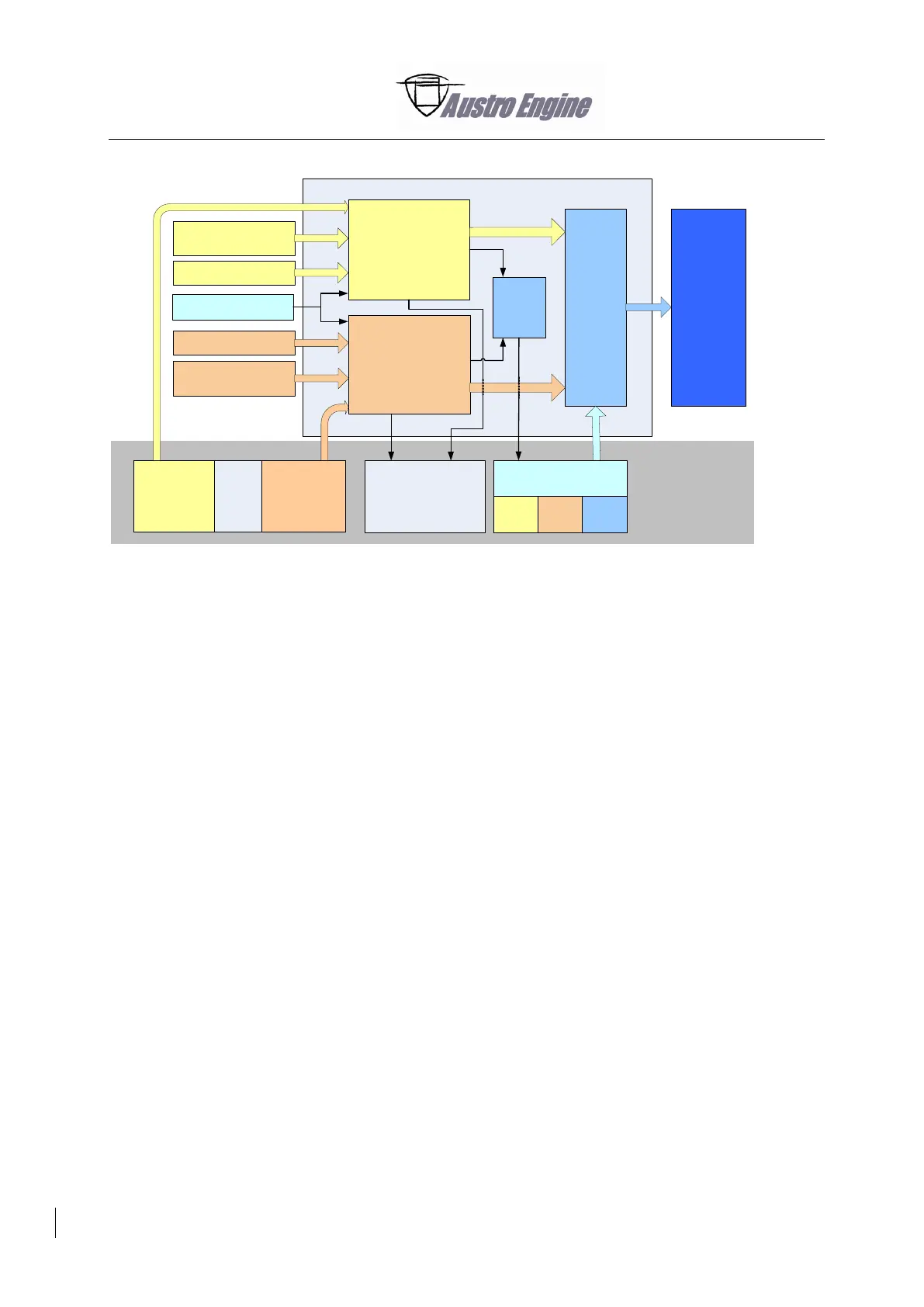
Fig. 76 - 2 EECU
Electrical Interfaces
- Outputs protected against
Short Circuit Ubatt
Short Circuit GND
- Diagnosis on Outputs and Sensor Inputs
Short Circuit Ubatt
Short Circuit GND
Open Load
- Sensor Inputs
Linearization of the input voltage
o According to the sensor characteristics
Monitoring of external interfaces
- External interfaces are monitored (sensors, actuators)
- A recognised failure (e.g. electrical) is internally reported
- Reported failures may inhibit other functions/monitoring
SW Function Montoring
- Separately calculated Values are used for monitoring the main Engine Control
Functions (e.g. Engine Speed Calculation, Injection Quantity Calculation)
EECU Hardware Monitoring provided
- Internal Supplies
- Internal Memories
- Internal communication
Failure monitoring / Fault Code Memory
- Reported Failures
are stored in the Fault Code Memory
o Up to 20 entries
Can lead in an ECU switch over
Can activate the ECU caution
Can cause a substitute function (e.g. substitute value)
ECU A
Voter
Sensors ECU A
Sensors ECU B
Shared Sensors
Relay
Matrix
Actuators
3way Cockpit
Switch
EECU
ECU A VoterECU B
Power Supply
ECU A
Power Supply
ECU B
ECU B
Engine
Indications /
Annunciations
A/C
Sensor A Sensor B
Power
Lever