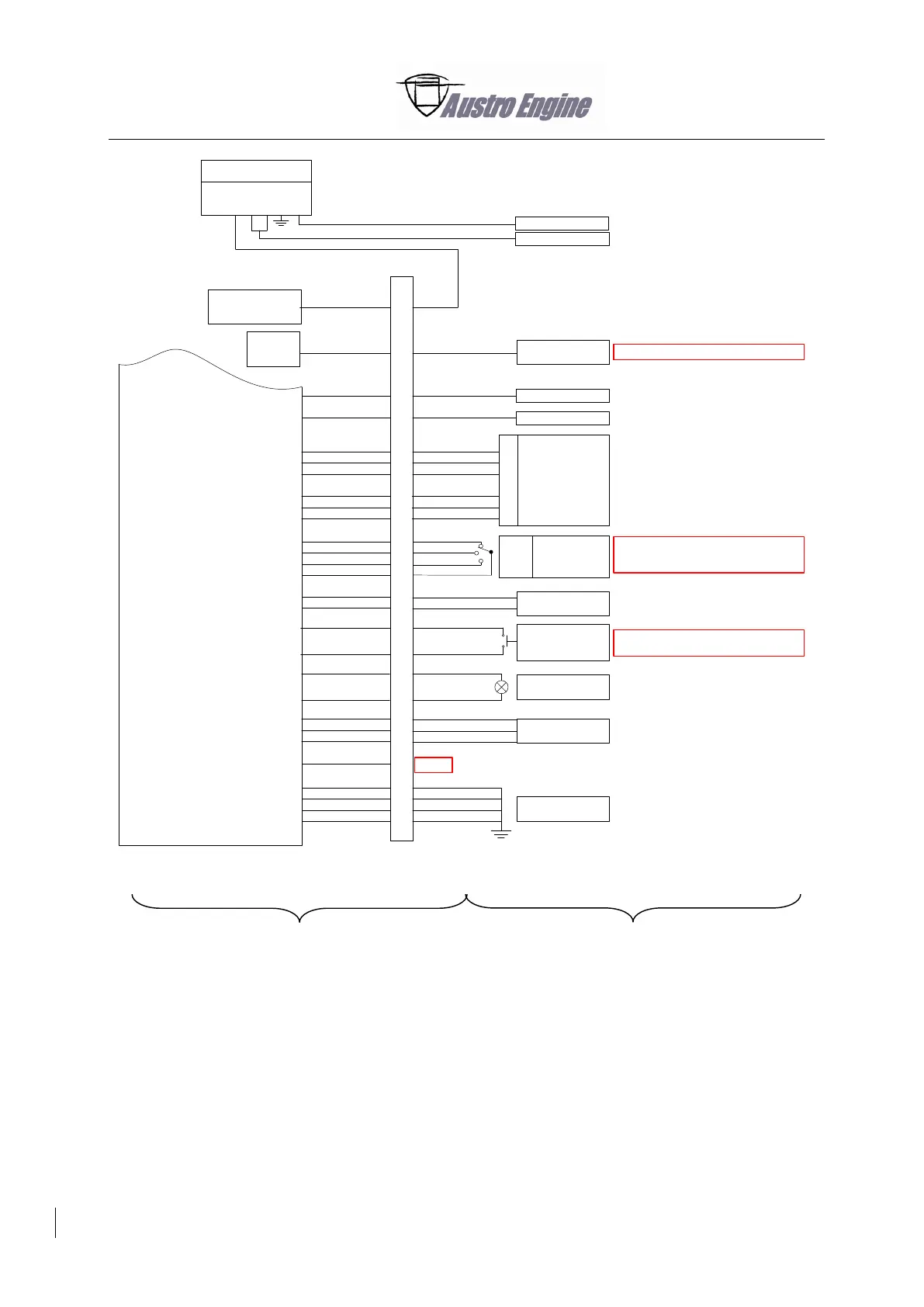
Alternator
Pin
4
1
2
3
7
11
12
8
10
9
13
15
16
14
17
18
19
20
21
22
23
24
25
26
27
28
29
30
CPC connector 2
EECU
Engine Master
ECU B
Synchronisation
Switch
(normally open)
Caution Lamp
ECU B
28V Power Supply
ECU B
GND Power Supply
ECU B
Example voter switch wiring:
Default is voter proposal, next position is
„ECU A“ then „ECU B“
Used in twin engine installations
Currently no function
Spare
Feather Valve
Switch
Used in twin engine installations
Fuel Pump Relay A
Fuel Pump Relay B
Feather
Valve
Sensor Supply
Sensor Signal
Sensor GND
Fuel Pump Relay Output A
Fuel Pump Relay Output B
Voter
ECU A
ECU B
Signal Input
Engine Master
Engine Master
Engine Synchronisation Signal
Engine Synchronisation GND
Caution Lamp Supply
Caution Lamp Signal
ECU B Power Supply
ECU B Power Supply
ECU B Power Supply
ECU B GND Supply
ECU B GND Supply
ECU B GND Supply
ECU B GND Supply
Sensor Supply
Sensor Signal
Sensor GND
Regulator
Plane Power R1224
Power Lever
Sensor
ECU B
Pin
1
4
2
6
3
5
Voter Switch
Voter
ECU A
ECU B
Enable Alternator
Lamp Alternator
IN
OUT
FIELD
ENABLE
AUX
GROUND
LAMP
Fig. 92 - 9