1126800 SmartPAC 2 with WPC Integration
Page 78 Chapter 2 Installing SmartPAC 2 and WPC
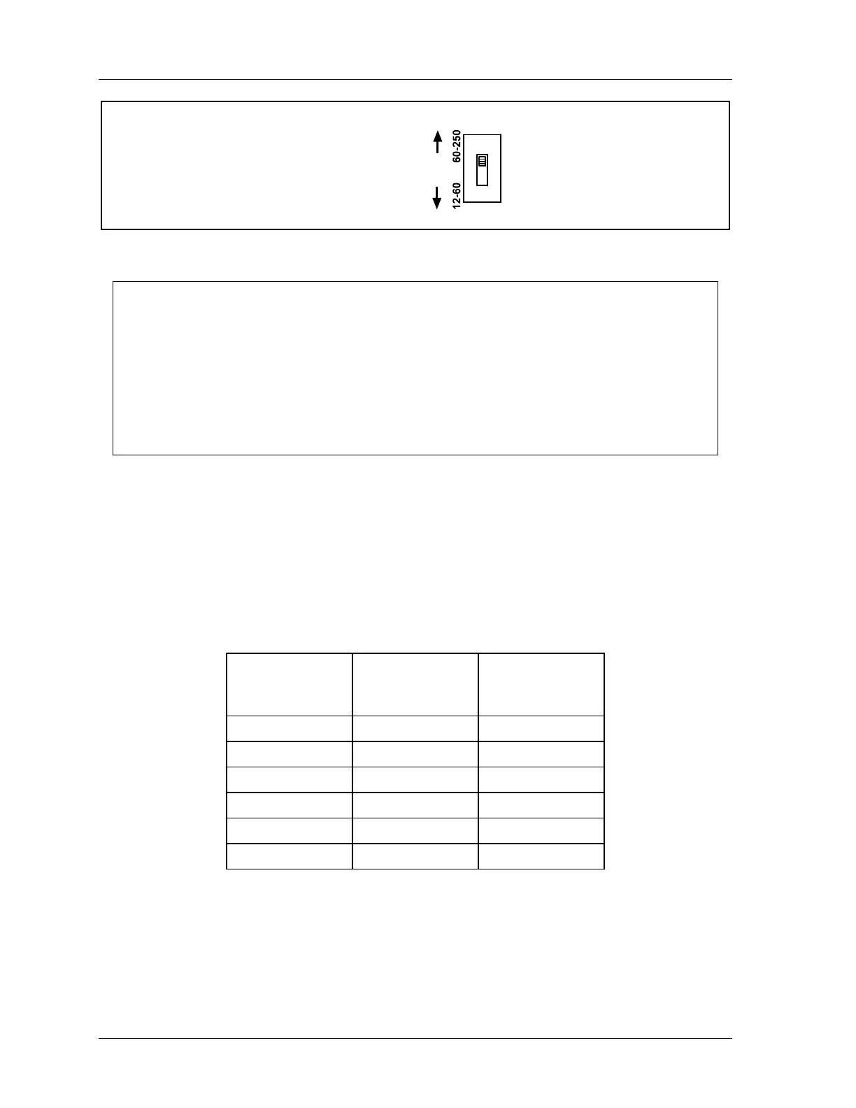
S101
Push switch down
for 12-60V
Push switch up
for 60-250V
Figure 2 - 21. Input check switch (S101)
NOTICE
HOW THE INPUT CHECK CIRCUIT DETECTS RESOLVER CHAIN BREAKAGE
When the dual safety valve relay is energized by the press control to start the press, voltage
will be produced in the input check circuit. This signals SmartPAC 2 that the press ram
should begin to move. If SmartPAC 2 gets no signals from the resolver within the start time
limit (resolver not turning), it opens the emergency stop circuit. A “loss of rotation” fault
message is displayed on the screen. The press could have started but the resolver belt or
chain broke or was significantly too loose so that the resolver shaft did not move. Other
possible reasons for the fault could be low air pressure to the clutch or a bad clutch.
2. Run the stop circuit, and input check circuit wires to SmartPAC 2 through flexible
liquid-tight conduit to the enclosure. Because SmartPAC 2 is rated NEMA 12 (protected
against dust and oil), you must use conduit of the same rating and make proper
connections to ensure NEMA 12 protection with the enclosure.
3. Locate connector TB102 for the stop circuits. It should be plugged into the socket.
Connect the wires for the stop circuits and input check SmartPAC 2 as shown in the table
below. (Also refer to Figure 1 at the end of the manual.)
Table 2 - 4. Wiring to Input Check and Stop Circuits
SmartPAC 2
TB102
Terminal
Wiring
Designation
WPC Control
Board
Pin #
205 A 41
206 B 29
207 E-Stop 68
208 E-Stop 67
209 Top Stop 80
210 Top Stop 79
9. Plug the connector back into its slot. Double check connections with markings at the
connector base to make sure that you did not wire it backwards.
10. Connect top stop, E-stop, and check input circuit wires at the press control.
 Loading...