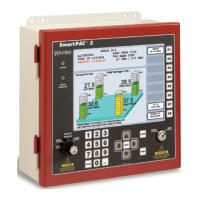
1126800 SmartPAC 2 with WPC Integration
Page 116 Chapter 2 Installing SmartPAC 2 and WPC
Prepare to Install Magnet for Overrun Limit Sensor
DANGER!
INJURY DURING SETUP
Keep all personnel away from the press during setup.
Ensure that there is no die or other tooling in the press during setup.
Failure to comply with these instructions will result in death or serious injury.
NOTICE
Refer to the following instructions, as necessary:
• Install the Overrun Limit Sensor Magnetic Switch, page 44
• Setting Switches,” page 242
• Switches 1 and 2 – Overrun Limit Switch Setting, page 242
• WPC LED map, Figure B at the end of the manual
NOTICE
The Top Stop Angle, which you just set, is the point in the stroke at which the Top Stop cam
turns on. The Top Stop cam stays on for 20° . The following instructions enable you to install
the Overrun Limit Sensor magnet so the overrun sensor turns on after the Top Stop cam
turns off.
1. In Run mode, select PRESS CONTROL. In the box below, write the Top Stop Angle.
_ ° Top Stop Angle
2. Check the box next to the range below that contains the Top Stop Angle. Go to the page
indicated.
Top Stop Angle 240°
°°
° or less: Go to next page.
Top Stop Angle
241°
°°
° - 270°
°°
° : Go to page 119.
Top Stop Angle
271°
°°
° - 300°
°°
° : Go to page 121.
Top Stop Angle
301°
°°
° or greater: Go to page 123.
 Loading...


