SmartPAC 2 with WPC Integration 1126800
SmartPAC 2 Run Mode Chapter 6 page 331
TOOL NUMBER 1234567
CHAIR BRACKET
SENSORS ENABLED
PART CNTR 0
USE CURSOR KEYS TO
MAKE SELECTIONS.
PRESS ENTER TO ACCESS
SELECTION.
COUNTERS
SHOW SENSORS
SHOW TIMING
SHOW STOPTIME
ADJUST SENSORS
ADJUST CAMS
LOAD NEW TOOL
PART CNTR 0
USE CURSOR KEYS TO
MAKE SELECTIONS.
PRESS ENTER TO ACCESS
SELECTION.
COUNTERS
BRAKE MONITOR
DIE PROTECTION
CAM SWITCH
PRESS SPEED
TOOL INFORMATION
ERROR LOG
LOAD NEW TOOL
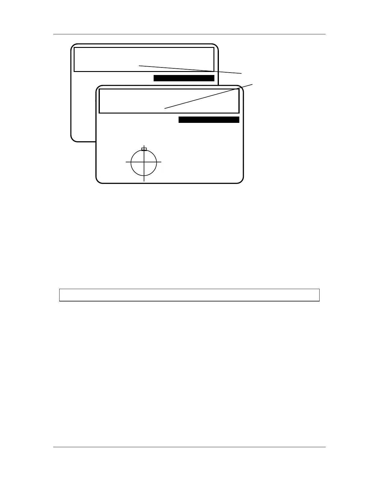
notice the sensor
status message
toggles from enabled
to disabled
TOOL NUMBER 1234567
CHAIR BRACKET
SENSORS DISABLED
ENABLE SENSORS
DISABLE SENSORS
Figure 6 - 8. Display Showing "Sensors Enabled" or "Sensors Disabled"
Setup Mode Message
If the setup mode circuit is connected and active, you will see this message at the top left of
the Run menu under the tool number: SENSORS IN SETUP MODE
This means green sensors are disabled. SmartPAC 2 will not send a stop signal to the press
when a green sensor signals a fault. The setup mode circuit is typically connected to the press
control. When the press control is set to INCH, the circuit is grounded and green sensors are
automatically disabled. To wire this circuit, see "Wiring Setup Mode Circuit,” page 94, and,
if necessary, the section after that, “Wiring a Sensor-disabled Output,” page 94.
For HELP press the HELP key located at the center of the cursor (arrow) keys.

 Loading...