1126800 SmartPAC 2 with WPC Integration
Page 264 Chapter 4 SmartPAC 2 Initialization Mode
COMMUNICATIONS
(INITIALIZATION – DIAGNOSTICS – COMMUNICATIONS)
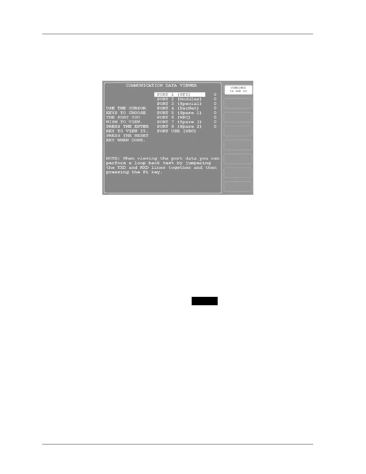
Figure 4 - 43. Communications
Use this screen when you need to verify the communications port between SmartPAC 2 and
the various installed modules, including SFI, Modules, PACNet
®
, etc.
To view normal communications between SmartPAC 2 and a module (e.g. SFI), you should
expect to see both "transmit " (TX) and "receive" (RX) data on the screen. See examples in
Figure 4 - 44. Press F2-Stop/Start Buffer if you want to examine the transmitted and/or
received data. If you do not see any data (or only partial data), this means that SmartPAC 2
and the other module are not communicating properly.
There are two formats for this display. See Figure 4 - 44 for examples. Press F1 to choose :
•
••
• Combined TX and RX – Transmit data appears as blue on a white background,
while Receive data shows as white on blue (
XXXXX). This view shows the data as it
is sent and received. Press F3-“Reset Buffer” to show the data from the beginning of
the buffer.
•
••
• Split TX and RX – Transmit data appears at the top of the screen. In this view, the
data shown always starts at the beginning of the buffer.
 Loading...