Figure 2 – Interfaces (Rear)
No. Description Notes
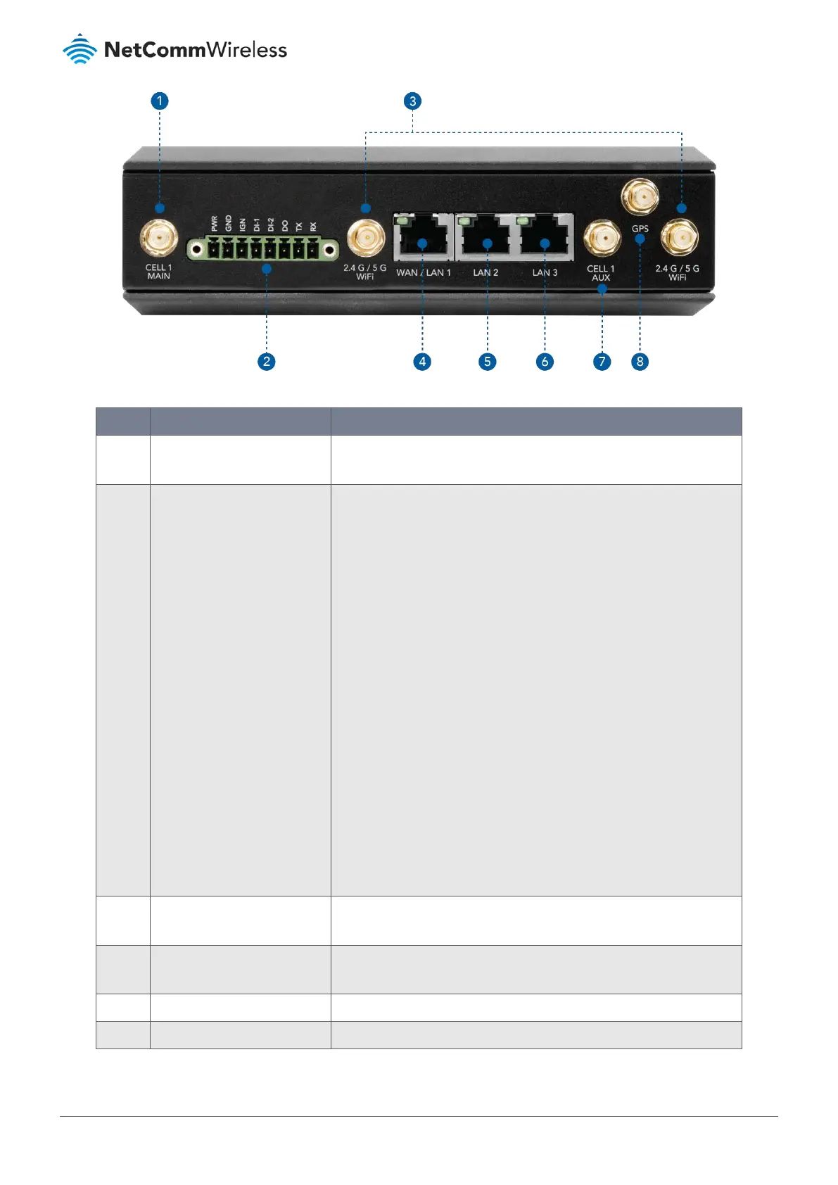
1 CELL1 Main Socket Connect one of the 3G/LTE Antennas here. If only using a single antenna,
ensure that it is connected to this port.
2 Power Terminal Block The Power Terminal Block provides the following ports:
• PWR (Power) – Supports 9V – 36V DC power input.
• GND (Ground) – Terminal for ground wire connection.
• IGN (Ignition) – Terminal used to connect to the ignition sense
wire of a vehicle.
• DI-1 (Digital Input 1)
o Trigger voltage (high) – 5V - 30V
o Trigger voltage (low) – 0V - 2.0V
• DI-2 (Digital Input 2)
o Trigger voltage (high) – 5V - 30V
o Trigger voltage (low) – 0V - 2.0V
• DO (Digital Output)
o Voltage (Relay mode) – Depends on external device,
maximum voltage is 30V.
o Maximum current – 1A.
• TX (Transmit) – Provides serial (RS-232) connectivity.
• RX (Receive) - Provides serial (RS-232) connectivity.
3 2.4GHz/5GHz WiFi Antenna
Socket
Connect the WiFi Antennas here.
4 WAN/LAN1 Port Auto MDI/MDIX RJ45 Port to connect local devices or an upstream
network when the port is set to WAN mode.
5 LAN2 Port Auto MDI/MDIX RJ45 Port to connect local devices.
6 LAN3 Port Auto MDI/MDIX RJ45 Port to connect local devices.
 Loading...