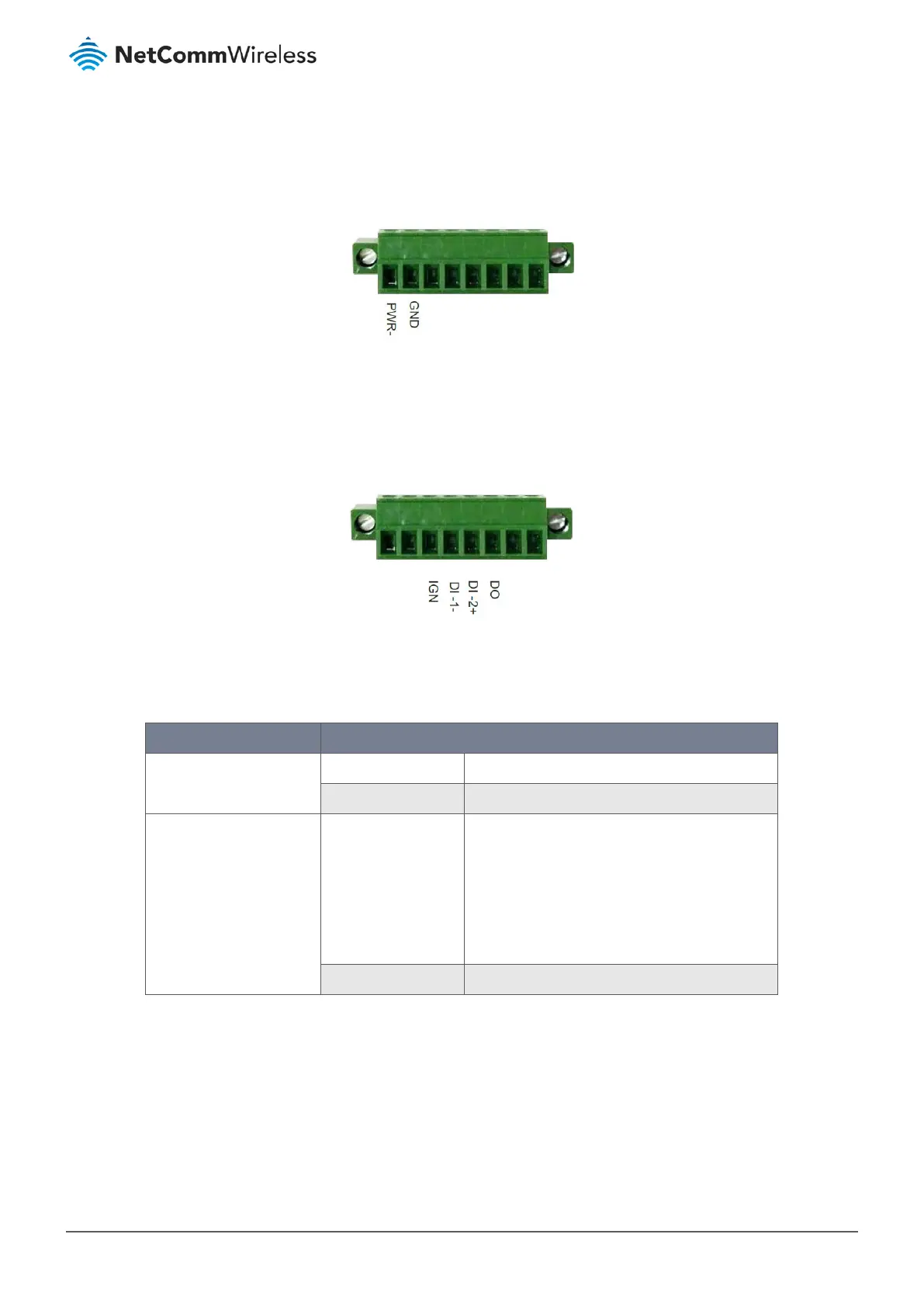
1.3.2.4 Connecting power
The NTC-400 Series Router accepts DC power in the range of 9 V to 36 V. Follow the picture below to ensure that the power
source is connected with the correct polarity.
Figure 3 – Power pins on terminal block
1.3.2.5 Connecting digital input/output devices and ignition
There are two digital input pins, one digital output pin and an ignition pin. Refer to the picture below to ensure that the pins
are correctly connected.
Figure 4 – Digital input, digital output and ignition pins on terminal block
1.3.2.6 I/O specifications
The table below lists the voltage specifications of the digital input and output ports.
Mode Specification
Digital Input (DI-1 and DI-2) Trigger voltage (high) Logic level 1: 5 V to 30 V
Normal voltage (low) Logical level 0: 0 V to 1.0 V
Digital Output (DO) Voltage (Relay mode) Logic level 1: Depends on external device.
Maximum voltage is 36 V.
Logic level 0: Floating, External pull-down resister
(10 K Ohm, ½ W) is required.
Note DO power is relayed from the “PWR” pin
on the 8-pin terminal block connector.
Maximum current 1 Amp @ 12 V, or 0.33 Amp @ 36 V
Table 3 – I/O specifications