EasyManuals Logo

Risco ProSYS series User Manual

Risco ProSYS series
232 pages
To Next Page IconTo Next Page
To Previous Page IconTo Previous Page
Page #25 background imageLoading...
Page #25 background image
ProSYS Installation and Programming Manual 25
Connecting the J10 Connector
POS NEG
Figure 8: Connecting the J10 Connector
The J10 connector (jumper) determines the UO1 connection (behavior), which is
normally used for an external siren connection, as follows:
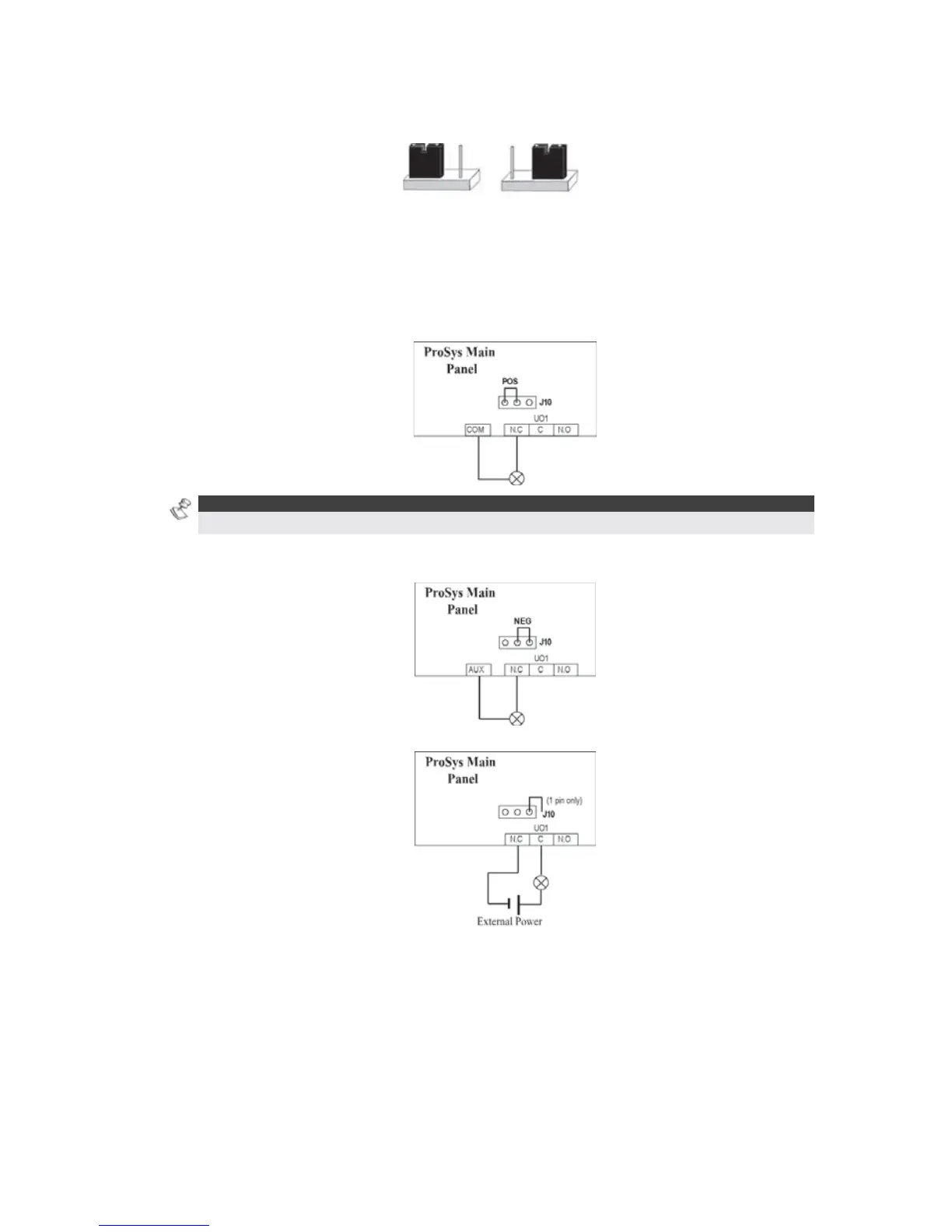
Positive (POS): When the J10 connector is placed on POS, the C terminal on UO1 receives
13.8V.
NOTE:
The maximum current for UO1 and the bell should not exceed 900mA.
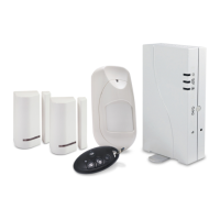
Negative (NEG): When the J10 connector is placed on NEG, the C terminal on UO1 receives
COM.
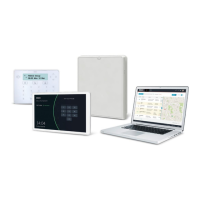
If the J10 connector is placed only on 1 pin, the UO1 acts as a dry contact.

Table of Contents

Questions and Answers:

Question and Answer IconNeed help?

Do you have a question about the Risco ProSYS series and is the answer not in the manual?

Risco ProSYS series Specifications

General IconGeneral
CommunicationIP, GSM, PSTN
Wireless ProtocolTwo-way wireless
Battery BackupYes
Remote ControlYes, via app
IntegrationRISCO Cloud

Related product manuals