30 ProSYS Installation and Programming Manual
Installing a Keypad
NOTE:
For information on installing the Touchscreen keypad, refer to the ProSYS Touchscreen Keypad
Instruction manual that is included with the product.
To install a keypad:
1 Open the Keypad Cover: Remove the back of the keypad cover, and using a
screwdriver, press in each of the retaining clips to separate the back cover from the
keypad. Take care not to touch the circuitry of the keypad buttons.
2 Set the Dip Switches: Program the keypad ID by setting the dip switches according to
the table displayed in
Figure 11 on page 29. Dip switch settings are per ID number
(01 = first keypad, 02 = second keypad, and so on).
3 Connect the BUS Wiring: Connect the wires from the appropriate terminals in the
keypad to the appropriate connector on the Main Panel's Expansion BUS terminals.
The connections are terminal-to-terminal with the terminals clearly marked. The wires
are color-coded, as follows:
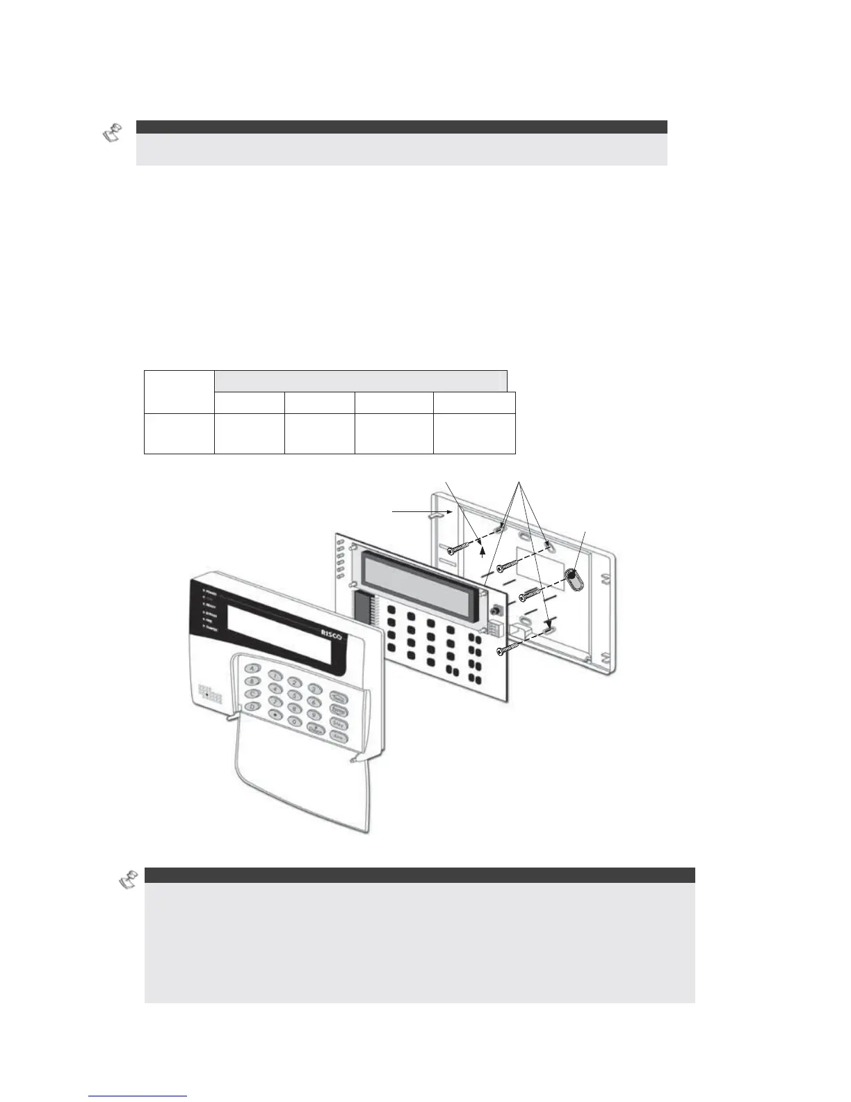
UP
Orientation arrow
Wall fixing points
Back panel
Tamper protected fixing
point
Figure 12: Keypad Installation Front View
NOTES:
A trimmer is located on the right side of the keypad (next to the dip switches) that enables you
to adjust the brightness and contrast of the LCD display. Therefore, it is recommended to leave
the keypad open while powering up in order to adjust the LCD display.
To prevent a possible drop in voltage due to multiple keypads and long wire runs, use a quality
4-conductor cable with an appropriate gauge size (refer to the table of gauge sizes in Chapter
1, Introducing ProSYS).
The maximum wire run permitted is 300 meters (1000 feet) for the total BUS wiring.
EXPANSION BUS TERMINALS
AUX COM BUS BUS
Color
RED BLK
(Black)
YEL
(Yellow)
GRN
(Green)