24 ProSYS Installation and Programming Manual
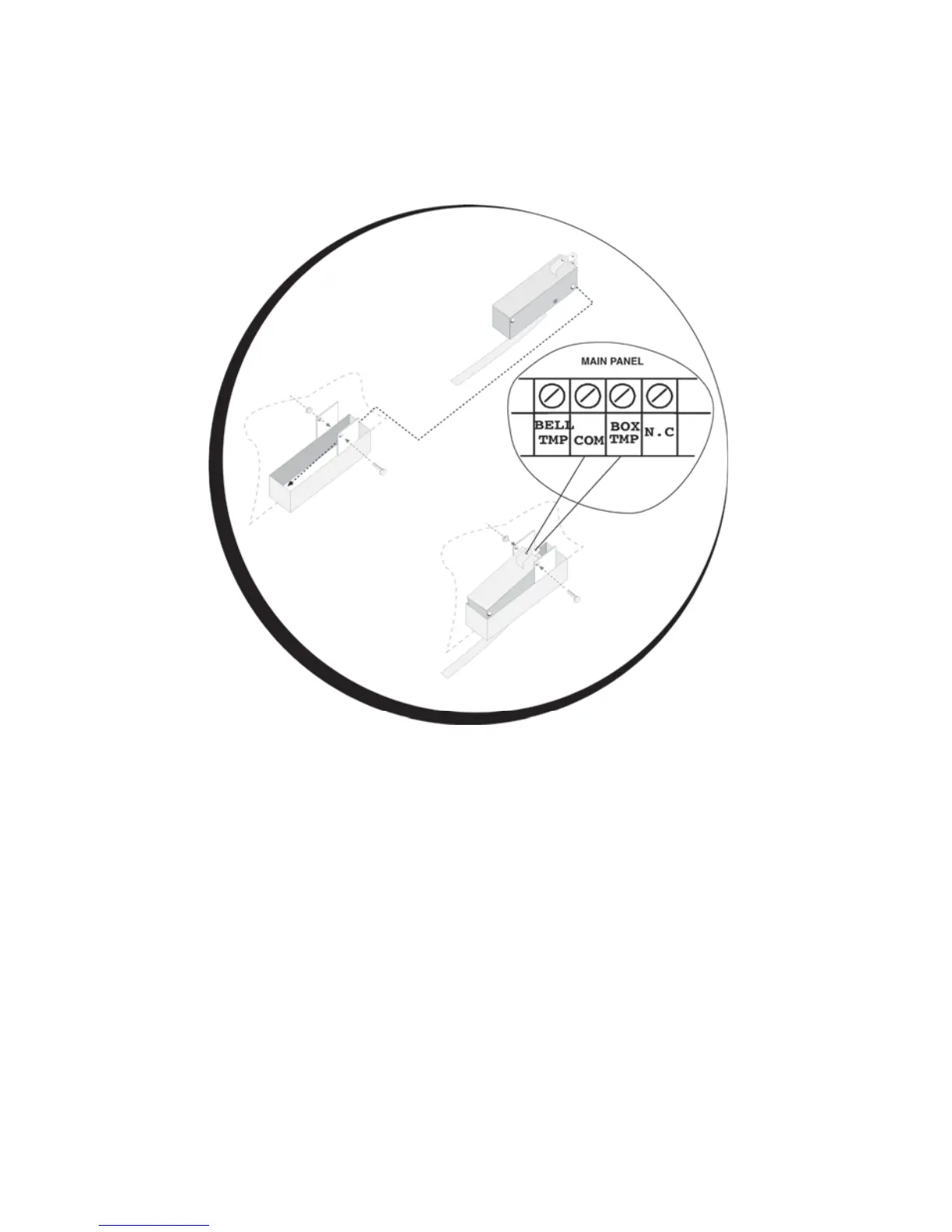
Wiring the Box Tamper
To wire the box tamper:
Connect the box tamper to the BOX TMP and COM terminals on the Main Panel, as
illustrated in
Figure 4 on page 18. Refer also to the diagram shown below.
Figure 7: Wiring the Box Tamper
Wiring External Triggerable Devices
To wire external triggerable devices:
Wire the external triggerable devices that you want to activate to the outputs UO1-UO6, as
follows:
O UO1: Refer to the J10 connector instructions, described in the next section. For
additional details, refer to Chapter 3, Installing External Modules and Devices.
O UO2-UO6: Connect the positive connection of the device to AUX (+) and the
negative connection to the UO's (-) terminals.