32 ProSYS Installation and Programming Manual
Wiring Utility Output Modules
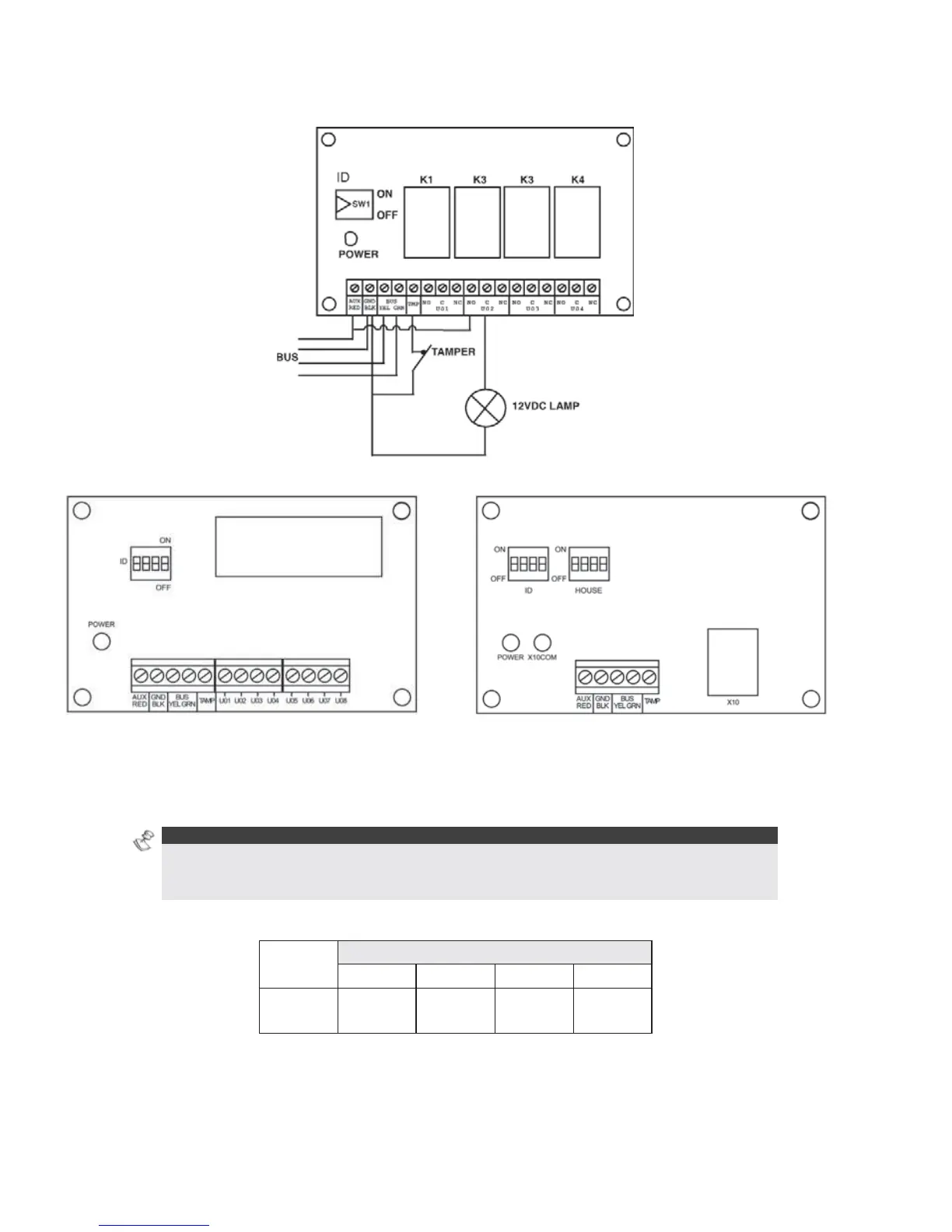
Figure 15: Utility Output Module UO4 (Showing an Example of UO4 Wiring)
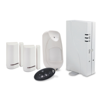
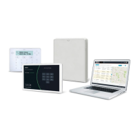
Figure 16: Utility Output Module E08 Figure 17: Utility Output Module X-10
To wire Utility Output modules:
1 Set the Dip Switches: Assign a unique ID to each Utility Output expansion module by setting
the dip switches, using
Figure 11 on page 29.
NOTE:
The ID for the first Utility Output expansion module is 01, for the second 02, and so on. The
first Utility Output in the Utility Output expansion module (defined as ID 01) will always be Utility
Output 07.
2 Connect the BUS Terminals: Connect the first four terminals at the left of the Utility
Output expansion module to the Main Panel's 4-wire BUS, as follows:
EXPANSION BUS TERMINALS
AUX COM BUS BUS
Color
RED BLK
(Black)
YEL
(Yellow)
GRN
(Green)
3 Set the Tamper (TAMP COM): The Utility Output expansion module can be contained in
a metal cabinet. Tamper the cabinet, as follows: