34 ProSYS Installation and Programming Manual
Wiring Power Supply Expansion Modules
ON
1234
ON
OF F
SW 1
BELL
LS
(PS LED)
(UO LED)
AC
AUX
RED
BELL LS
+ -
TAMP
BUS
YEL GRN
COM
BLK
BUS
BELL/ LS
(Bell/Loudspeaker
Jumper)
OC
(Over Current LED)
BAT
(Battery Jumper)
PS
Battery
Connections
Loudspeaker/
Bell
Power to Accessories
and Detectors
Transformer
1234
1234
ON
N.O
N.C
C
UO 1
C
UO 2
N.O
N.C
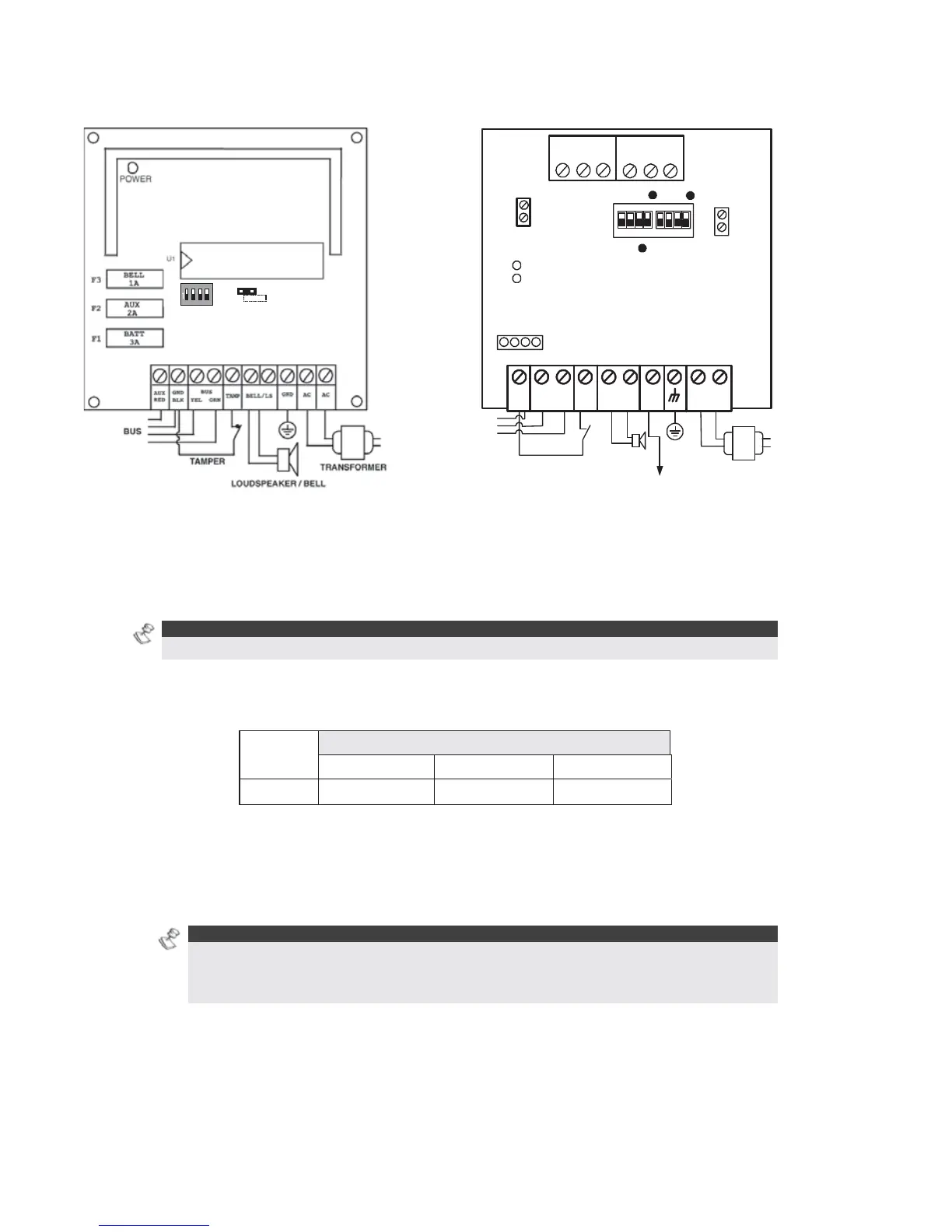
Figure 18: 1.5A Power Supply Module PS Figure 19: 3A Power Supply Module PS
To wire Power Supply expansion modules:
1 Set the Dip Switches: Assign a unique ID to each Power Supply expansion module
by setting the dip switches, using
Figure 11 on page 29.
NOTE:
The ID for the first Power Supply expansion module is 01, for the second 02, and so on.
2 Connect the BUS Terminals: Connect only three of the first four terminals at the left of
the Power Supply expansion module to the Main Panel's 4-wire BUS, as follows (refer also
to Figure 2-3 in Chapter 2, Mounting and Wiring the Main Panel):
EXPANSION BUS TERMINALS
COM BUS BUS
Color
BLK (Black) YEL (Yellow) GRN (Green)
3 Set the Tamper (TAMP COM): The Power Supply expansion module can be contained in
a metal cabinet. Tamper the cabinet, as follows:
O Connect one (or more) normally open momentary-action pushbutton switches in a
series between the TAMP and COM terminals.
NOTES:
It is not necessary to use a tamper switch if another module sharing the same cabinet is
equipped with one.
Do NOT use an End-of-Line Resistor in the tamper switch circuit.
O If a tamper switch is not used, connect a wire jumper between the two terminals.
4 Connect the Internal Siren BELL/LS (+) (-):
O Connect a suitable wire to the internal device(s) to be driven by the Power Supply
expansion module (bell, electronic siren, or loudspeaker).