8 ProSYS Installation and Programming Manual
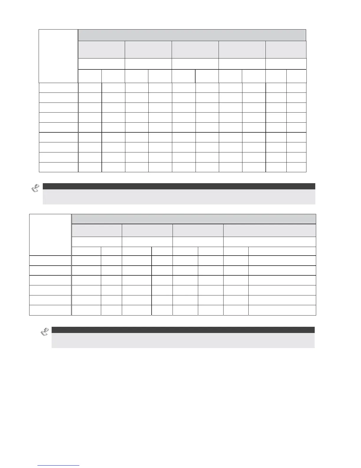
Total
Auxiliary
Power
(Max Current
Draw per
Branch)
Desired Wire Gauge in Particular Branch
32/02 mm
18 AWG
28/02 mm
19 AWG
24/02 mm
20 AWG
16/02 mm
22 AWG
7/02 mm
24 AWG
Max Run Max Run Max Run Max Run Max Run
Meters Feet Meters Feet Meters Feet Meters Feet Meters Feet
20mA 1195 3920 945 3100 750 2460 472 1550 296 970
30mA 793 2600 628 2060 500 1640 314 1030 197 646
40mA 597 1960 472 1550 375 1230 236 775 148 485
50mA 478 1568 378 1240 300 984 189 620 118 388
60mA 296 1300 314 1030 250 820 157 515 98 323
70mA 341 1120 270 886 214 703 135 443 84 277
80mA 299 980 237 775 187 615 118 388 74 243
90mA 264 867 209 687 166 547 105 343 66 215
100mA 239 784 189 620 123 492 94 310 59 194
Table A-4: Total Auxiliary Power
NOTE:
The wire lengths indicated represent the one-way distance between the source of power and the last detector
in the branch.
Max External
Siren Current
(Max current
draw per
branch)
Desired Wire Gauge in Particular Branch
32/02 mm 28/02 mm 24/02 mm 16/02 mm
Max Run Max Run Max Run Max Run
Meters Feet Meters Feet Meters Feet Meters Feet
100mA 238 780 191 625 151 495 94 310
200mA 229 390 95 313 76 248 47 155
300mA 79 260 63 208 50 165 31 103
400mA 59 195 48 157 38 124 24 78
500mA 48 156 38 125 30 99 19 62
650mA 37 120 29 96 23 76 15 48
Table A-5: Maximum External Siren Current
NOTE:
The wire lengths indicated represent the one-way distance between the ProSYS and the external siren in
the branch.