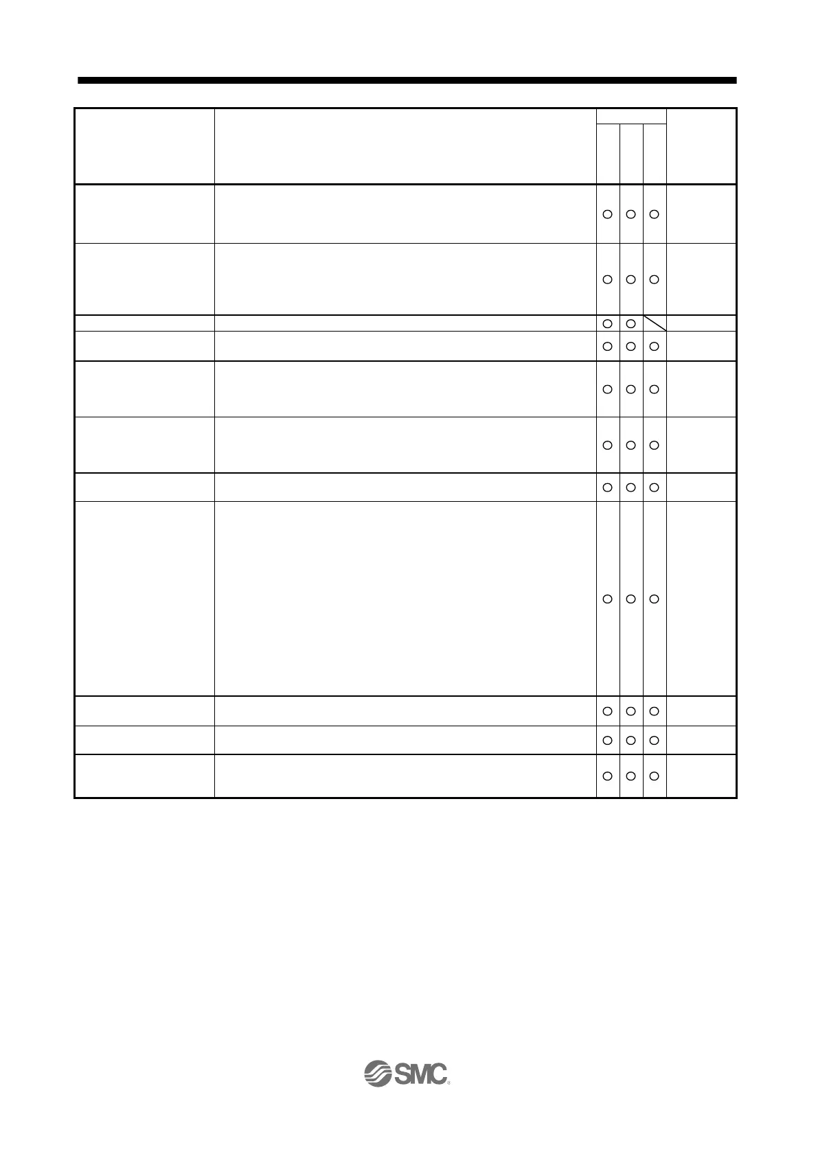
Output signal selection
(device settings)
The output devices including MBR (Electromagnetic brake interlock) can be
assigned to certain pins of the CN1 connector.
[Pr. PD23] to
[Pr. PD26]
[Pr. PD28]
[Pr. PD47]
Output signal (DO) forced
output
Output signal can be forced on/off independently of the servo status.
Use this function for checking output signal wiring, etc.
Section 3.1.8
Section 3.2.8
section 4.5.8
section
18.5.9
Supports only A-axis/B-axis pulse trains.
Servo motor torque can be limited to any value.
Servo status is shown on the 5-digit, 7-segment LED display.
Section
3.1.2
Section
3.2.2
External I/O signal display
On/off statuses of external I/O signals are shown on the display.
Section
3.1.7
Section
3.2.7
If an alarm has occurred, the corresponding alarm number is outputted in 3-
bit code.
Jog operation/positioning operation/motor-less operation/DO forced
output/program operation/single-step feed
However, setup software (MR Configurator2
TM
) is necessary for positioning
operation, program operation, and single-step feed.
Section
3.1.8
Section
3.1.9
Section
3.2.8
Section
3.2.9
section 4.5.8
section 4.5.9
section
18.5.9
section
18.5.10
Servo status is outputted in terms of voltage in real time.
setup software (MR
Configurator2
TM
)
Using a personal computer, you can perform the parameter setting, test
operation, monitoring, and others.
Gain adjustment is performed just by one click on a certain button on setup
software (MR Configurator2
TM
) or operation section.
section 6.2
section
18.5.4

 Loading...