EasyManuals Logo

SMC Networks LECSB2-T Series User Manual

SMC Networks LECSB2-T Series
945 pages
To Next Page IconTo Next Page
To Previous Page IconTo Previous Page
Page #537 background imageLoading...
Page #537 background image
16 - 37
16. POSITIONING MODE
Device
Symbol
Connector
pin No.
Function and application
I/O
division
Control
mode
CP/
CL
PS
M code 1 (bit 0)
MCD00
This device can be used in the point table method.
These signals can be checked with output devices of the communication
function. (Refer to section 10.2 (1).)
To use these signals, set " _ _ 1 _" in [Pr. Po12].
The signals output M code simultaneously with CPO (Rough match) on.
Set M code with point tables.
The code represents one digit of decimal using four digits of binary.
The following shows correspondence of each digit and device.
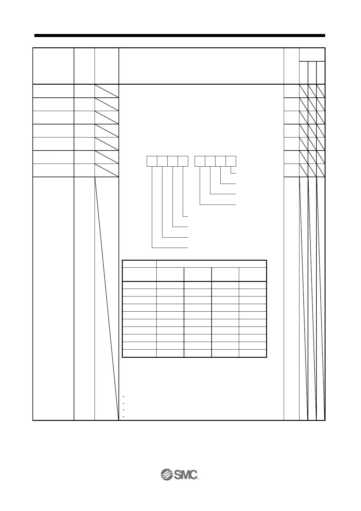
DO-
1
M code 2 (bit 1)
MCD01
DO-
1
M code 3 (bit 2)
MCD02
DO-
1
M code 4 (bit 3)
MCD03
DO-
1
M code 5 (bit 4)
MCD10
DO-
1
M code 6 (bit 5)
MCD11
DO-
1
M code 7 (bit 6)
MCD12
DO-
1
M code 8 (bit 7)
MCD13
DO-
1
M code
Device (Note)
First/second
digit
MCD03/
MCD13
MCD02/
MCD12
MCD01/
MCD11
MCD00/
MCD10
0
0
0
0
0
1
0
0
0
1
2
0
0
1
0
3
0
0
1
1
4
0
1
0
0
5
0
1
0
1
6
0
1
1
0
7
0
1
1
1
8
1
0
0
0
9
1
0
0
1
Note.
0: Off
1: On
MCD00 to MCD03 and MCD10 to MCD13 will turn off with the following
status.
Power on
Servo-off
Manual operation mode
At alarm occurrence
bit3 bit2 bit1 bit0 bit3 bit2 bit1 bit0
MCD00
MCD01
MCD02
MCD03
MCD10
MCD11
MCD12
MCD13
Second digit First digit

Table of Contents

Questions and Answers:

Question and Answer IconNeed help?

Do you have a question about the SMC Networks LECSB2-T Series and is the answer not in the manual?

SMC Networks LECSB2-T Series Specifications

General IconGeneral
BrandSMC Networks
ModelLECSB2-T Series
CategoryDC Drives
LanguageEnglish