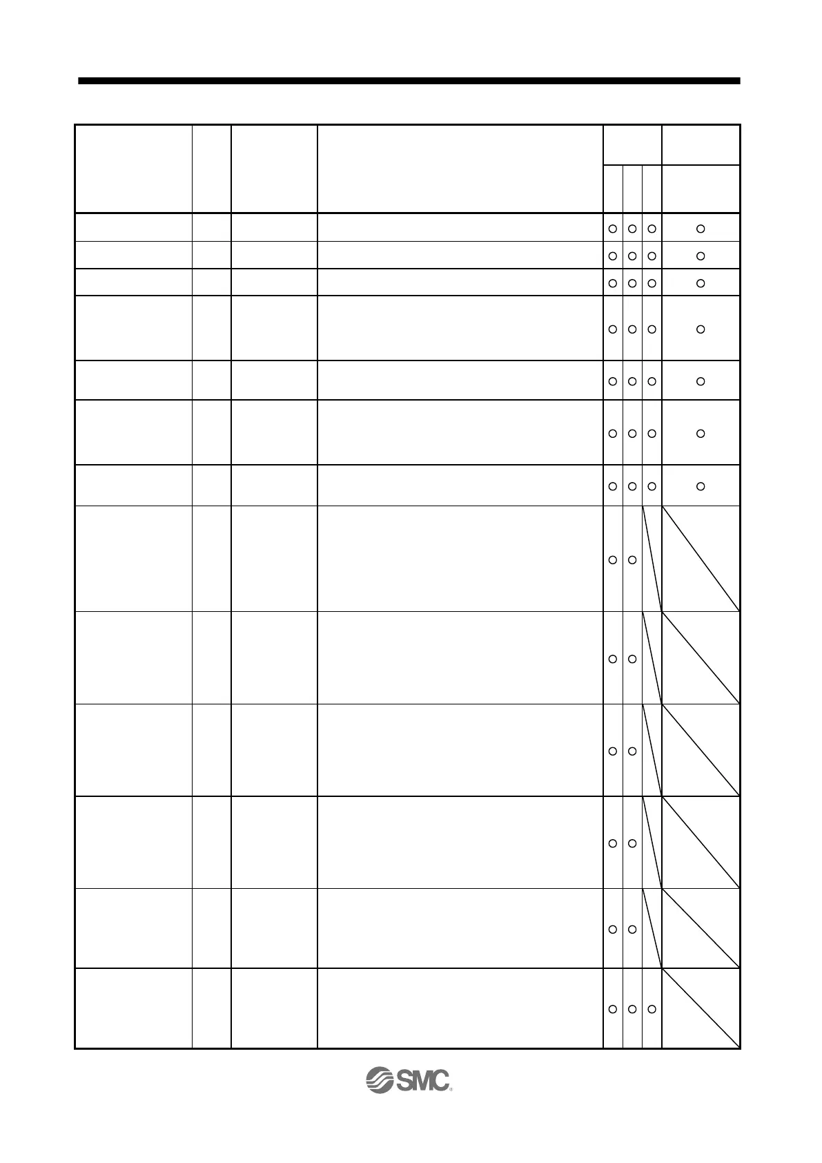
Settling time is displayed. When it exceeds 1000 ms, "1000" will
be displayed.
Oscillation detection
frequency
Frequency at the time of oscillation detection is displayed.
Number of tough drive
operations
The number of tough drive functions activated is displayed.
Unit power consumption
1 (1 W unit)
Unit power consumption is displayed by increment of 1 W.
Positive value indicates power running, and negative value
indicates regeneration. The values in excess of ±99999 can be
counted. However, the counter shows only the lower five digits
of the actual value since the driver display is five digits.
Unit power consumption
2 (1 kW unit)
Unit power consumption is displayed by increment of 1 kW.
Positive value indicates power running, and negative value
indicates regeneration.
Unit total power
consumption 1
(1 Wh unit)
Unit total power consumption is displayed by increment of 1 Wh.
Positive value is cumulated during power running and negative
value during regeneration. The values in excess of ±99999 can
be counted. However, the counter shows only the lower five
digits of the actual value since the driver display is five digits.
Unit total power
consumption 2
(100 kWh unit)
Unit total power consumption is displayed by increment of 100
kWh. Positive value is cumulated during power running and
negative value during regeneration.
Load-side encoder
Cumulative feedback
pulses
Feedback pulses from the load-side encoder are counted and
displayed.
The values in excess of ±99999 can be counted. However, the
counter shows only the lower five digits of the actual value since
the driver display is five digits.
Press the "SET" button to reset the display value to zero.
The value of minus is indicated by the lit decimal points in the
upper four digits.
Load-side encoder
Droop pulses
Droop pulses of the deviation counter between a load-side
encoder and a command are displayed. When the count
exceeds ±99999, it starts from 0.
Negative value is indicated by the lit decimal points in the upper
four digits.
The display shows the average droop pulse value of 128-time
sampling at the rate of 444 [μs].
Load-side encoder
information 1
(1 pulse unit)
The Z-phase counter of a load-side encoder is displayed in the
encoder pulse unit.
For an incremental linear encoder, the Z-phase counter is
displayed. The value is counted up from 0 based on the home
position (reference mark). For an absolute position linear
encoder, the encoder absolute position is displayed.
When the count exceeds 99999, it starts from 0.
Load-side encoder
information 1
(100000 pulses unit)
The Z-phase counter of a load-side encoder is displayed by
increments of 100000 pulses.
For an incremental linear encoder, the Z-phase counter is
displayed. The value is counted up from 0 based on the home
position (reference mark). For an absolute position linear
encoder, the encoder absolute position is displayed.
When the count exceeds 99999, it starts from 0.
Load-side encoder
information 2
When an incremental linear encoder is used as the load-side
encoder, the display shows 0.
When an absolute position linear encoder is used as the load-
side encoder, the display shows 0.
When a rotary encoder is used as the load-side encoder, the
display shows the multi-revolution counter value of the encoder.
The Z-phase counter is displayed in the encoder pulse unit.
For an incremental linear encoder, the Z-phase counter is
displayed. The value is counted up from 0 based on the home
position (reference mark). For an absolute position linear
encoder, the encoder absolute position is displayed.
When the count exceeds 99999, it starts from 0.
 Loading...