The Z-phase counter is displayed by increments of 100000
pulses.
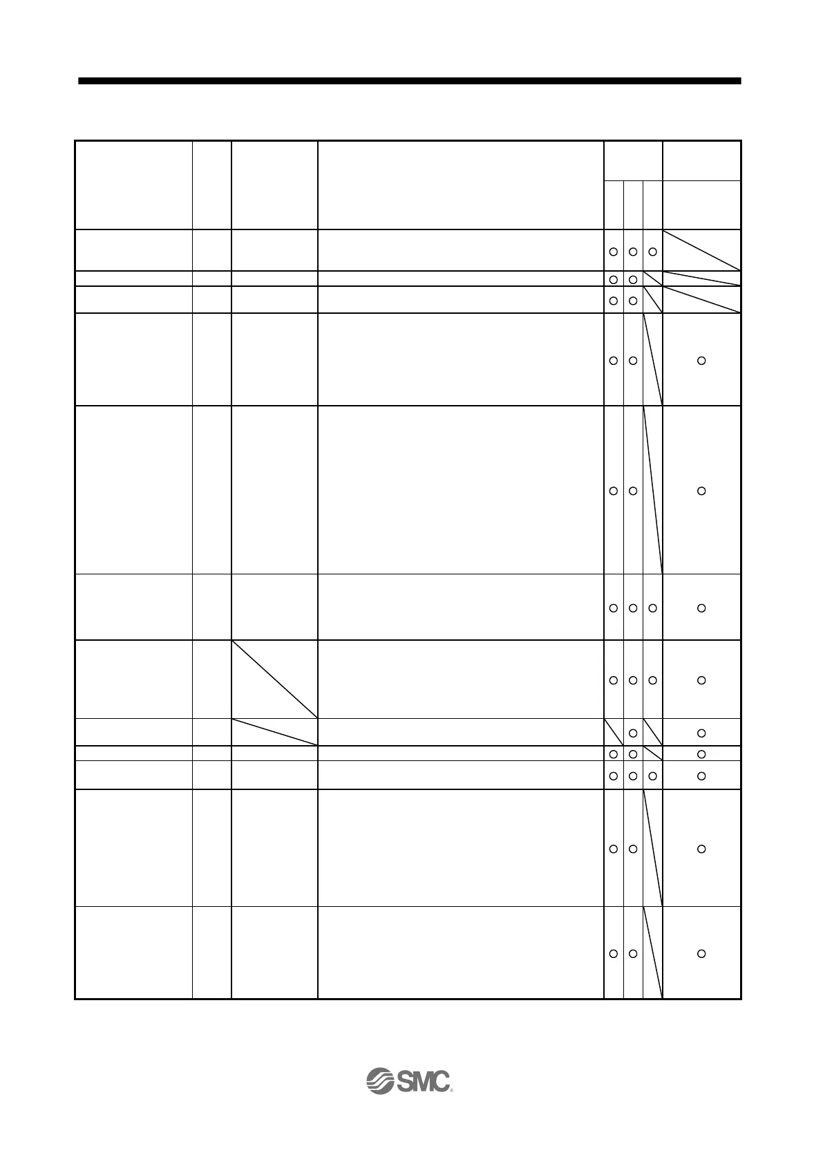
When the count exceeds 99999, it starts from 0.
The servo motor electrical angle is displayed.
The servo motor electrical angle is displayed by increments of
100000 pulses.
10
STM
μm
10
(STM-4)
inch
10
-3
degree
pulse
(Note 2)
When "_ _ 0 _" (positioning display) is set in [Pr. PT26], the
current position is displayed as machine home position is 0.
When "_ _ 1 _" (roll feed display) is set in [Pr. PT26], the actual
current position is displayed as start position is 0.
The values in excess of ±99999 can be counted. However, the
counter shows only the lower five digits of the actual value since
the driver display is five digits.
10
STM
μm
10
(STM-4)
inch
10
-3
degree
pulse
(Note 2)
When "_ _ 0 _" (positioning display) is set in [Pr. PT26], the
command current position is displayed as machine home
position is 0.
When "_ _ 1 _" (roll feed display) is set in [Pr. PT26], turning on
the start signal starts counting from 0 and a command current
position to the target position is displayed in the automatic
mode.
The command positions of the selected point table are displayed
at a stop. At the manual mode, the command positions of the
selected point table are displayed.
The values in excess of ±99999 can be counted. However, the
counter shows only the lower five digits of the actual value since
the driver display is five digits.
Command remaining
distance
10
STM
μm
10
(STM-4)
inch
10
-3
degree
pulse
(Note 2)
Indicates the remaining distance to the command position of the
currently selected point table, program and station.
The values in excess of ±99999 can be counted. However, the
counter shows only the lower five digits of the actual value since
the driver display is five digits.
Point table No./program
No./command station
position
For the point table method and program method, the point table
and program No. currently being executed are displayed. The
selected number is displayed during a temporary stop or manual
operation.
For the indexer method, the command next station position is
displayed.
The step No. of the program currently being executed is
displayed. At a stop, 0 is displayed.
The analog override voltage is displayed.
The setting value of the override is displayed.
When the override is disabled, 100% is displayed.
Cam axis one cycle
current value
10
STM
μm
10
(STM-4)
inch
10
-3
degree
pulse
(Note 4)
The current position in one cycle of CAM axis is displayed with
the range of "0 to (cam axis one cycle length - 1)", the cam axis
one cycle current value which is calculated from the travel
distance inputted to the cam axis. When the simple cam function
is disabled, 0 is always displayed.
The values in excess of ±99999 can be counted. However, the
counter shows only the lower five digits of the actual value since
the driver display is five digits.
Refer to section 12.1.8 for detecting point.
10
STM
μm
10
(STM-4)
inch
10
-3
degree
pulse
(Note 2)
A feed current value which is the standard position of the cam
operation is displayed. When the simple cam function is
disabled, 0 is always displayed.
The values in excess of ±99999 can be counted. However, the
counter shows only the lower five digits of the actual value since
the driver display is five digits.
Refer to section 12.1.8 for detecting point.

 Loading...