Cam axis feed current
value
10
STM
μm
10
(STM-4)
inch
10
-3
degree
pulse
(Note 2)
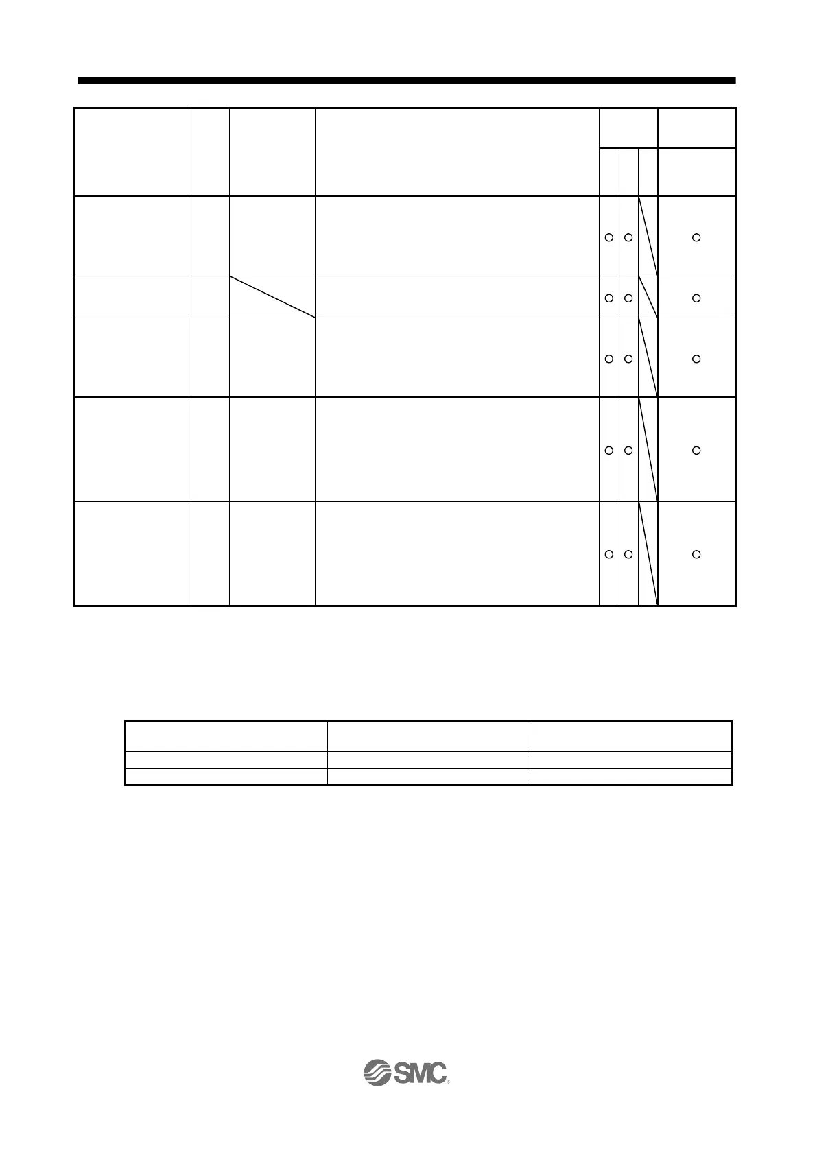
A feed current value during the cam axis control is displayed.
When the simple cam function is disabled, 0 is always displayed.
The values in excess of ±99999 can be counted. However, the
counter shows only the lower five digits of the actual value since
the driver display is five digits.
Refer to section 12.1.8 for detecting point.
Cam No. in execution is displayed.
When the simple cam function is disabled, 0 is always displayed.
Refer to section 12.1.8 for detecting point.
Cam stroke amount in
execution
10
STM
μm
10
(STM-4)
inch
10
-3
degree
pulse
(Note 2)
Cam stroke amount in execution is displayed. When the simple
cam function is disabled, 0 is always displayed.
The values in excess of ±99999 can be counted. However, the
counter shows only the lower five digits of the actual value since
the driver display is five digits.
Refer to section 12.1.8 for detecting point.
10
STM
μm
10
(STM-4)
inch
10
-3
degree
pulse
(Note 4)
A current value of the input axis (synchronous encoder axis or
servo input axis) is displayed. Unit is increment of input axis
position. When the simple cam function is disabled, 0 is always
displayed.
The values in excess of ±99999 can be counted. However, the
counter shows only the lower five digits of the actual value since
the driver display is five digits.
Refer to section 12.1.8 for detecting point.
Main axis one cycle
current value
10
STM
μm
10
(STM-4)
inch
10
-3
degree
pulse
(Note 4)
The input travel amount of the input axis is displayed within the
range of "0 and (cam axis one cycle length setting - 1)". Unit is
an increment of cam axis one cycle. When the simple cam
function is disabled, 0 is always displayed.
The values in excess of ±99999 can be counted. However, the
counter shows only the lower five digits of the actual value since
the driver display is five digits.
Refer to section 12.1.8 for detecting point.
CP: Positioning mode (point table method)
CL: Positioning mode (program method)
PS: Positioning mode (indexer method)
The unit can be selected from μm/inch/degree/pulse with [Pr. PT01].
Depending on the setting of [Cam control data No. 30 Main shaft input axis selection], the parameters used to set the unit and
feed length multiplication will change as follows. For details of each parameter, refer to section 7.2.9 and 12.1.7 (3).
Setting of [Cam control data No. 30]
Parameter for the unit setting
Parameter for the feed length
multiplication setting
[Cam control data No. 14]
[Cam control data No. 14]

 Loading...