Interlock line
At no time should you bypass the interlock feature of the 2600B. Safe operation requires a
separate interlock circuit that meets the requirements of the application to reliably protect the
operator from exposed voltages. Bypassing the interlock could expose the operator to
hazardous voltages that could result in personal injury or death.
The 2611B, 2612B, 2614B, 2634B, 2635B, or 2636B interlock (INT) line of the digital I/O can be used
with a switch in the test fixture or component handler. With proper use, power is removed from the
DUT when the lid of the fixture is opened. See Interlock operation (on page 4-43, on page 4-44) and
Interlock (on page 4-44) for more details.
Use interlock cable assembly CA-558 to connect the 2600B interlock to either a Model 8010 High
Power Device Test Fixture or to the Model 2657A-LIM-3 LO Interconnect Module (refer to the
connection information supplied with the device).
Digital I/O configuration
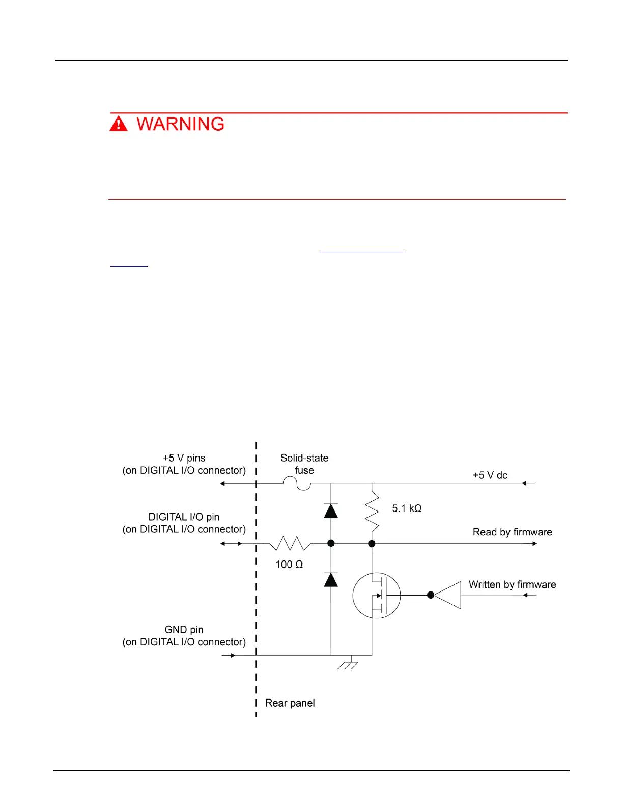
The following figure shows the basic configuration of the digital I/O port. Writing a 1 to a line sets that
line high (~ +5 V). Writing a 0 to a line sets that line low (~0 V). Note that an external device pulls an
I/O line low by shorting it to ground, so that a device must be able to sink at least 960 μA per I/O line.
Figure 57: Digital I/O interface schematic

 Loading...


