Using TSP-Link trigger lines for digital I/O
Each trigger line is an open-drain signal. When using the TSP-Link
®
trigger lines for digital I/O, any
node that sets the programmed line state to zero (0) causes all nodes to read 0 from the line state.
This occurs regardless of the programmed line state of any other node. Refer to the table in Digital
I/O bit weighting (on page 4-41) for digital bit-weight values.
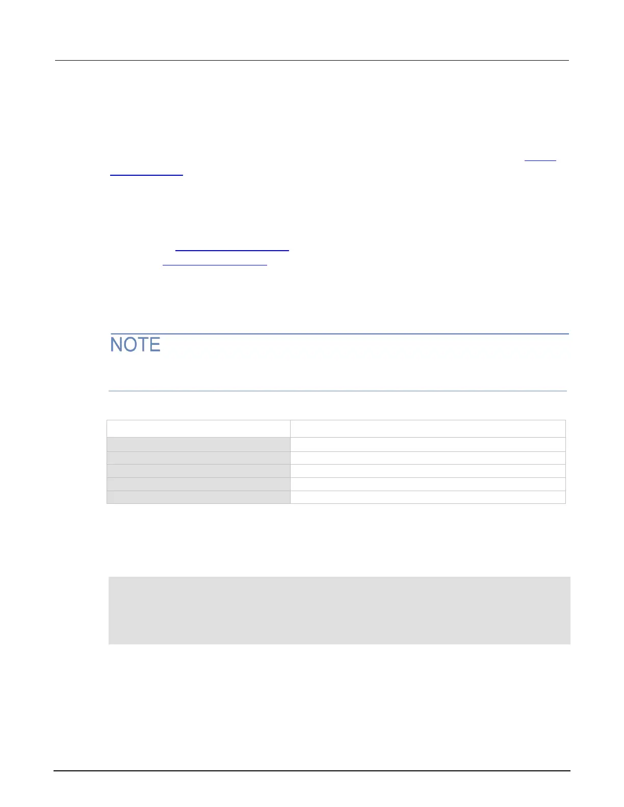
Remote TSP-Link trigger line commands
Commands that control and access the TSP-Link
®
trigger line port are summarized in the following
table. See the TSP command reference (on page 9-1) for complete details on these commands. See
the table in Digital I/O bit weighting (on page 4-41) for the decimal and hexadecimal values used to
control and access the digital I/O port and individual lines.
Use the commands in following table to perform basic steady-state digital I/O operations; for example,
you can program the 2600B to read and write to a specific TSP-Link trigger line or to the entire port.
The TSP-Link trigger lines can be used for both input and output. You must write a 1 to all TSP-Link
trigger lines that are used as inputs.
Programming example
The programming example below illustrates how to set bit B1 of the TSP-Link digital I/O port high,
and then read the entire port value:
-- Set the TSP-Link trigger line to the trigger bypass mode.
tsplink.trigger[1].mode = tsplink.TRIG_BYPASS
-- Set bit B1 high.
tsplink.writebit(1, 1)
-- Read I/O port.
data = tsplink.readport()

 Loading...


