Figure 75: Current source limit line (2611B, 2612B, 2614B, 2634B, 2635B, and 2636B)
Load considerations (I-source)
The boundaries within which the SMU operates depend on the load (device-under-test, or DUT) that
is connected to its output. The following figures shows operation examples for resistive loads that are
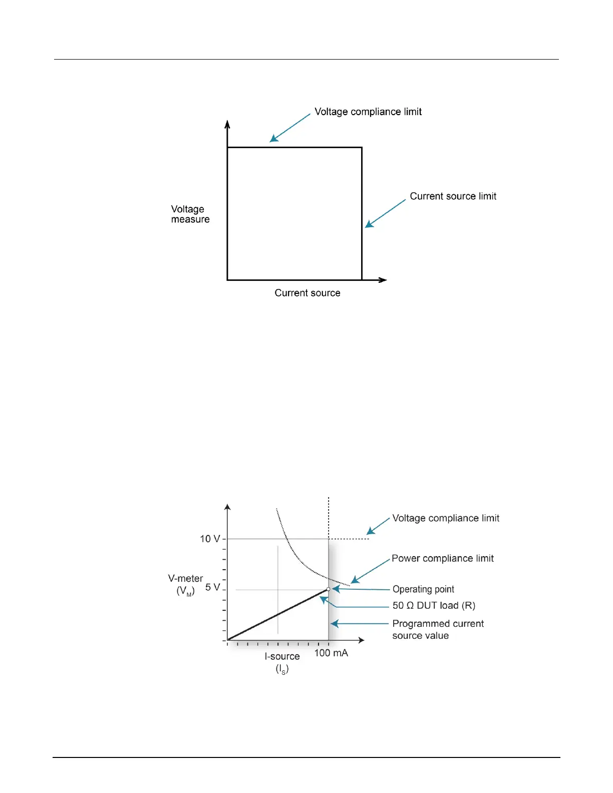
50 Ω and 200 Ω. For these examples, the SMU is programmed to source 100 mA and limit voltage
(10 V).
In the following figure, the SMU is sourcing 100 mA to the 50 Ω load and subsequently measures 5 V.
The SMU is also programmed to limit power to 600 mW. As shown, the load line for 50 Ω intersects
the 100 mA current source line at 5 V. The voltage compliance limit and the power compliance limit
are not reached (the SMU is not limited through its compliance settings).
Figure 76: Normal current source operation

 Loading...


