Series 2600B System SourceMeter® instrument Reference Manual Section 5: Theory of operation
2600BS-901-01 Rev. F/August 2021 5-3
The instrument output amplifier voltage. This constant can be found in the tables in Maximum duty cycle
equation (on page 5-3).
The voltage level the instrument is attempting to force while at the pulse level.
When operating in quadrants 1 or 3 (sourcing power), the sign of this voltage must be positive when
used in the power equations.
When operating in quadrants 2 or 4 (sinking power), the sign of this voltage must be negative when
used in the power equations.
The current flowing through the instrument channel while at the pulse level.
The voltage level the instrument is attempting to force while at the bias level.
When operating in quadrants 1 or 3 (sourcing power), the sign of this voltage must be positive when
used in the power equations.
When operating in quadrants 2 or 4 (sinking power), the sign of this voltage must be negative when
used in the power equations.
The current flowing through the instrument channel while at the bias level.
The maximum power generated in an instrument channel that can be properly dissipated by the
instrument cooling system, measured in watts. For the 2600B, this constant equals 56.
= T
AMB
- 30
This factor represents the number of watts the instrument is derated when operating in environments
above 30 °C. The maximum output power of each instrument channel is reduced by 1 W per degree C
above 30 °C.
P
DER
is 0 when the ambient temperature is below 30 °C.
The ambient temperature of the instrument operating environment.
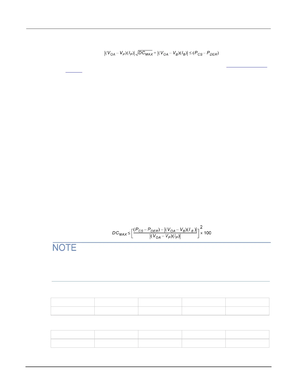
Maximum duty cycle equation
The following equation applies to both channels, sinking or sourcing power simultaneously. If a duty
cycle less than 100% is required to avoid overheating, the maximum on-time must be less than
10 seconds.
When attempting to determine the maximum duty cycle, where the off state is 0 V or 0 A:
▪ I
B
is 0
▪ I
P
and V
P
are the voltage and current levels when the instrument is on
2601B, 2602B, and 2604B maximum duty cycle equation constants
2611B, 2612B, 2614B, 2634B, 2635B, and 2636B maximum duty cycle equation constants

 Loading...


