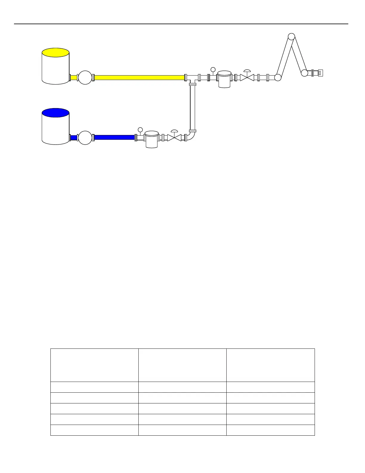
Figure 5.5 Simple Side-Stream Application
Side-Steam blending is similar to Ratio blending in that two or more components are delivered simultaneously to
achieve a blend. Each component incorporates its own control valve and flow meter. In a side-stream
configuration, minor component(s) are injected upstream of the major component’s flow meter (primary meter).
Flow through the primary meter flows at the rate dictated by the preset-level High Flow Rate parameter. The flow
rate of the side-stream component tracks the flow rate of the primary meter. The side-stream seeks to maintain
its rate at a pre-programmed ratio of the rate that is being controlled through the primary meter/valve. The
primary meter measures the commingled major and minor components.
5.5.1 SIMPLE SIDE-STREAM BLENDER CONFIGURATION
When configuring a load arm to be a side-stream blender, begin at the preset-level. At the preset-level, define the
number of flow meters and components (liquids) that will be delivered through the load arm. A maximum of five
flow meters and eight components can be assigned to a load arm. Set the Blending Type parameter found at the
preset-level to RATIO.
At the meter-level configuration, default values can typically be used for the primary meter (Meter 1). When
configuring parameters for Meter 2, enter a value in the Side-Stream On Mtr# parameter. By entering a value of 1
for this parameter, Meter 2 is designated to be a side-stream of Meter 1. It will probably be necessary to adjust
the Flow and Dead Band rates of Meter 2, since the side-stream meter is typically smaller than the primary
stream’s meter. Reference the table for suggested settings. The Maximum Flow Rate and Minimum Flow Rate
parameters for Meter 2 will also need to be adjusted to match the flow meter manufacturer’s specifications.
At the component-level configuration, the components are assigned to a particular meter, using the Meter#
parameter. Component 1 is typically assigned to Meter 1 and Component 2 is typically assigned to Meter 2.