Firmware Version 3/4.31.37
A maximum of 16 additives (2 additives on SMP) can be routed through a single injector. Regardless of the
configuration, a maximum of 16 additives (2 additives on SMP) can be assigned to each load arm; only one
additive can be delivered through the common injector during a single load.
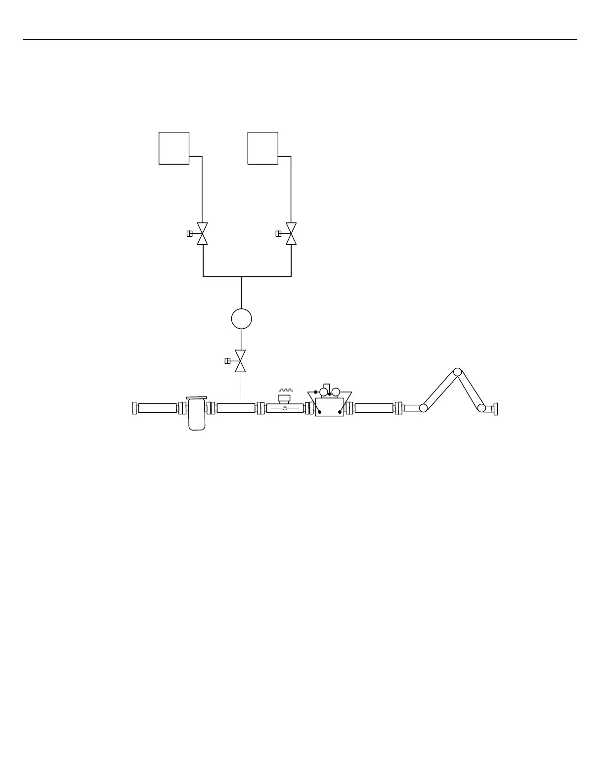
The Common Meter algorithm has been designed to accommodate two hydraulic configurations: One scheme
employs an Injector Valve and Additive Block Valves. The second scheme uses Additive Block Valves only.
Figure 6.3 Common Injector Valve Scheme
In the diagram above, the solenoid-operated Additive Block Valves are used to select the additive that is to be
delivered. One of these valves will open when the start button is pressed. It will close when the additive quantity
required for the entire load has been delivered.
While loading, the Additive Injector Valve opens and closes periodically to inject additive into the product stream.
The Additive Injector Valve will be open long enough to deliver the quantity specified by the Additive Volume per
Injection parameter.
The following schematic illustrates the electrical relationship between the injection outputs and the solenoid
operated valves. The outputs are represented by switches in the diagram. During a load, only one of the Additive
Block Valve outputs will be active. The output will remain active, energizing its corresponding solenoid for the
load’s duration. The Additive Injection output will close and open periodically as injections are required,
energizing and de-energizing the injector solenoid.