EasyManuals Logo

Toptech Systems MultiLoad II User Manual

Toptech Systems MultiLoad II
515 pages
To Next Page IconTo Next Page
To Previous Page IconTo Previous Page
Page #206 background imageLoading...
Page #206 background image
Chapter 6 – Additive Control
206
Firmware Version 3/4.31.37
L1
L2
Additive Injection
Output
Injector Valve
Solenoid
Additive Block Valve
Output-Add #1
Additive Block Valve
Solenoid-Add #1
Additive Block Valve
Output-Add #2
Additive Block Valve
Solenoid-Add #2
Figure 6.4 Electrical Schematic using Injector Valve
6.5.10 ADDITIVE BLOCK VALVES ONLY
Add #1 Add #2
M
Additive
Meter
Additive Block Valve
Add #1
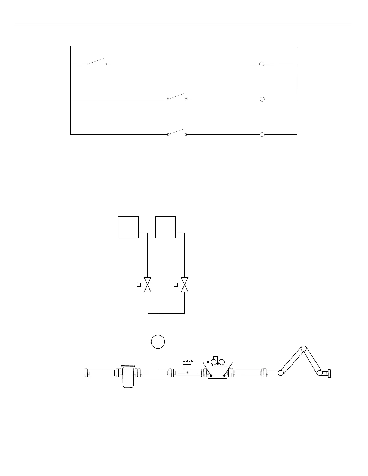
Figure 6.5 Scheme using Block Valves to Inject
In the diagram above, the solenoid-operated Additive Block Valves are used to select the additive that is to be
delivered. In contrast to the previous scheme, an additive Injector Valve is not used. During a load, the Additive
Block Valve of the selected additive is opened only when an injection is commanded. This is accomplished by
wiring the Additive Block Valve output in series with the Additive Injection output. Refer to the schematic below.

Table of Contents

Questions and Answers:

Question and Answer IconNeed help?

Do you have a question about the Toptech Systems MultiLoad II and is the answer not in the manual?

Toptech Systems MultiLoad II Specifications

General IconGeneral
BrandToptech Systems
ModelMultiLoad II
CategoryControl Unit
LanguageEnglish

Related product manuals