Chapter 5 – Product Flow Control
Firmware Version 3/4.31.37
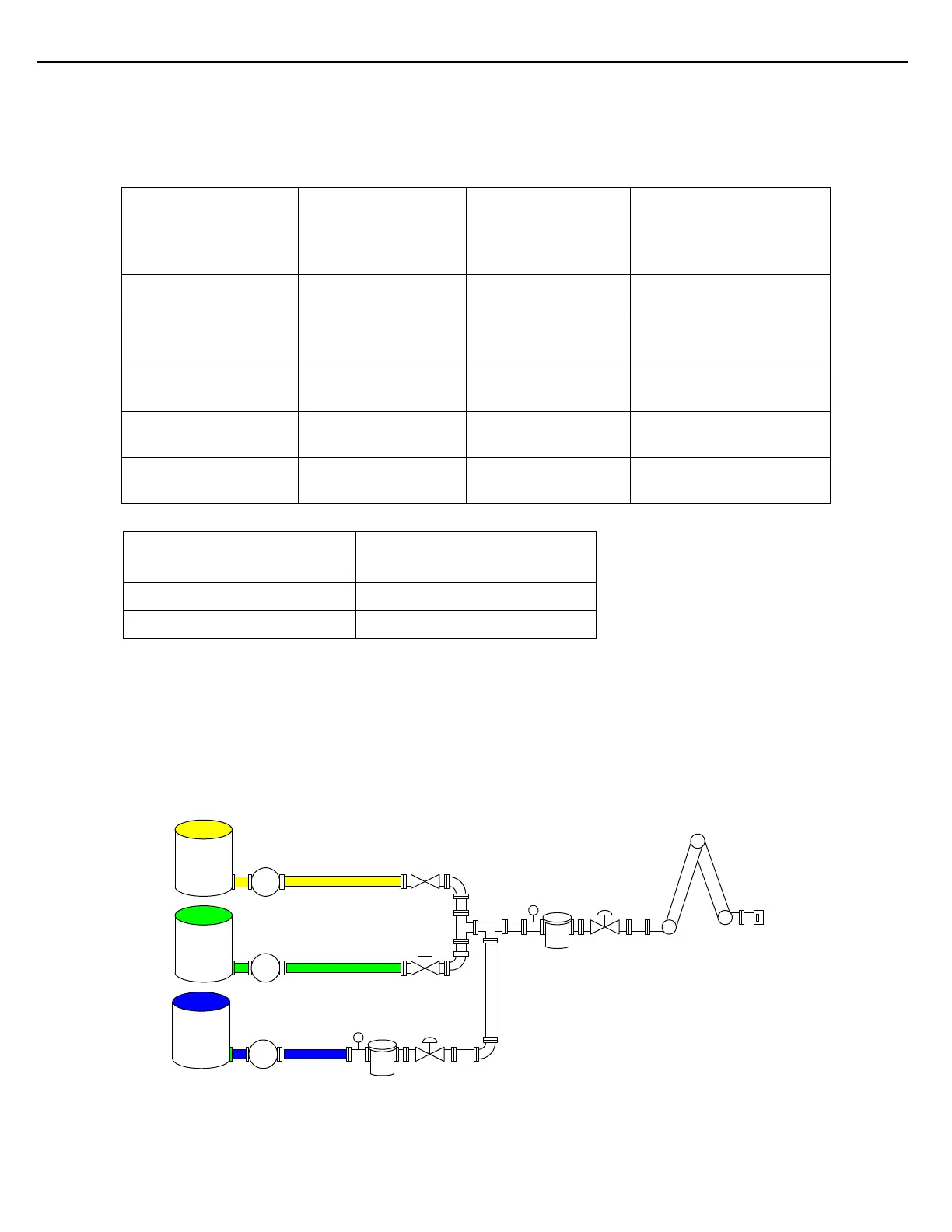
The following table identifies the configuration parameters necessary to support the diagram in Figure 5.3. Meter
#2 and Meter #3 are both designated as side-stream meters of Meter #1. Four side-stream meters could
potentially be assigned to this load arm.
Components 1-3
Component-To-Meter
Assignment “Meter #”
Param.
Side-Stream on
Meter # = 1
Side-Stream on
Meter # = 1
Figure 5.8 Multiple Side-Stream Configuration
5.6.2 SEQUENTIAL BLENDING WITH SIDE-STREAM
Sequential blending with a side stream component is a hybrid-blending scheme. As each component is delivered
in turn through the primary stream, a minor component is being blended into the primary stream, upstream of the
primary flow meter.
P
P
Premium
Regular
BV
T1
CV
M1
BV
Comp #1
Comp #2
P
Ethanol
Comp #3
T2
CV
M2
Figure 5.9 Sequential Blending with Side-Stream Application
Weights & Measures
Meter #2
Weights & Measures
Meter #3
Maximum Flow Rate 100 gpm
Maximum Flow Rate 100 gpm