Firmware Version 3/4.31.37
Component Setup
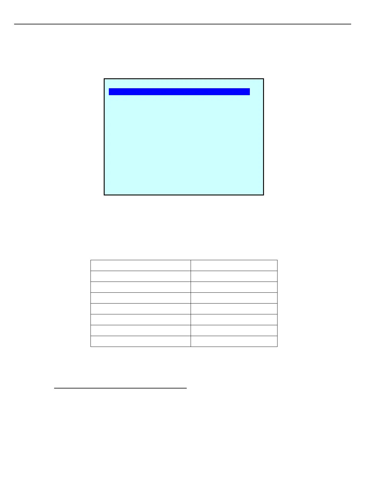
For ratio blending, each component must have its own meter. Assign the component #1 to Meter #1. Assign the
component #2 to Meter #2, and so on.
The Pump Run port assignment for the component is also configured on this screen. Additionally, there is a
Pump Kill output that can be assigned to provide a signal to remove power from the pump. An option also exists
to configure a Pump Status signal to provide positive verification that a pump is running. The pump related input
and output signals can be assigned to any Flow Control Module.
The 1st Stage Trip and the 2nd Stage Trip parameters are also defined on this Screen. Enter the volume and
rate that defines the 1st Stage Trip and 2nd Stage Trips.
For detailed parameter descriptions, please refer to General Configuration chapter topic “Component Setup.”
5.5 SIDE-STREAM BLENDING (EXCLUDING SMP)
PRE #1 CMP #1 (Base 001 ) SETUP
Meter#: 1
High Flow Rate: 600
1st Stage Trip Vol: 70
1st Stage Flow Rate: 225
2nd Stage Trip Volume: 20
2nd Stage Flow Rate: 150
Final Trip Vol: 1.15
Final Trip Max Time: 5.000
Final Trip Vol Lock: DISABLD
Unauth Flow Alrm Vol: 10
W&M Recipe Percentage: 0.00
BlkValve Open Rate: 0
BlkValve Open Delay: 0
B.V. Open Alrm Time: 10
Next Prev Exit Enter