Chapter 4 – General Configuration
Firmware Version 3/4.31.37
Recipe Output Bit 2 FCM# parameter allows the selection of a port that will send an
output signal. This output signal will represent the third bit of a binary representation
for the selection of the current loaded authorized preset product.
Recipe Output Bit 3 FCM# parameter allows the selection of a port that will send an
output signal. This output signal will represent the fourth bit of a binary representation
for the selection of the current loaded authorized preset product.
Recipe Output Bit 4 FCM# parameter allows the selection of a port that will send an
output signal. This output signal will represent the fifth bit of a binary representation
for the selection of the current loaded authorized preset product.
4.8.3 METER SETUP
Use the Meter Setup functions to configure the characteristics of a product meter.
Further details about flow control can be found in Chapter 5.
Meter flow rates are configured in the Weights & Measures -> Meter section and can be found in Chapter 8.
Navigate to this screen as: Program Mode -> Configuration -> Equipment Setup -> Select Parameter Level ->
Meter
All Weights and Measures controlled values are displayed in red both on the screen and in this manual.
The Meter Setup screen displays:
Assign a Flow Control Module (FCM) for the selected product flow meter. When using
an internal I/O Board, 0 is the only valid entry. Port 4 will automatically be selected as
the Channel A meter input signal. If a Channel B meter input is used, it must be
connected to Port 5. To activate Channel B, see Weights and Measures parameter
"Quad Check Enable." The digital control valve upstream and downstream outputs
will automatically be assigned to Port 2 and Port 3 respectively.
Side-Stream on Mtr#
(Excluding SMP & SCS)
If this meter will be a side-stream meter, use this parameter to identify the primary
meter stream into which the side-stream meter will be flowing. See Side-Stream
Configuration section for more details (Section 5.5).
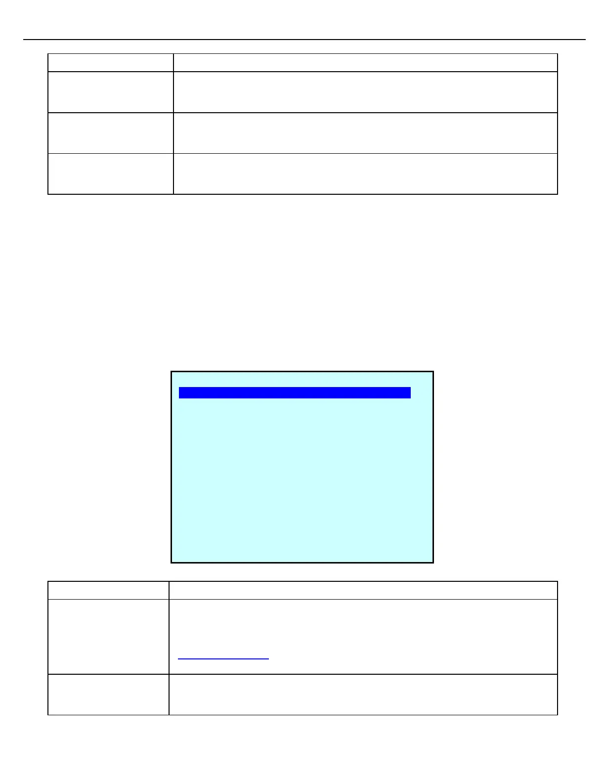
PRE #1 MTR #1 SETUP
Flow Control Module#: 0
Side-Stream on Mtr# 0
Side-Strm on Any Mtr# DISABLD
Meter Address: 0
Meter Type: VOL PUL
Max Quad Errors: 10
Reset Quad Errors: 10000
Low Flow Alarm Rate: 10
Low Flow Alarm Time: 10.000
Excess Flw Alrm Rate: 800
Minimum Flow Rate: 50
Maximum Flow Rate: 650
Low Flow DB Rate: 40
High Flow DB Rate: 40
Next Prev Exit Enter