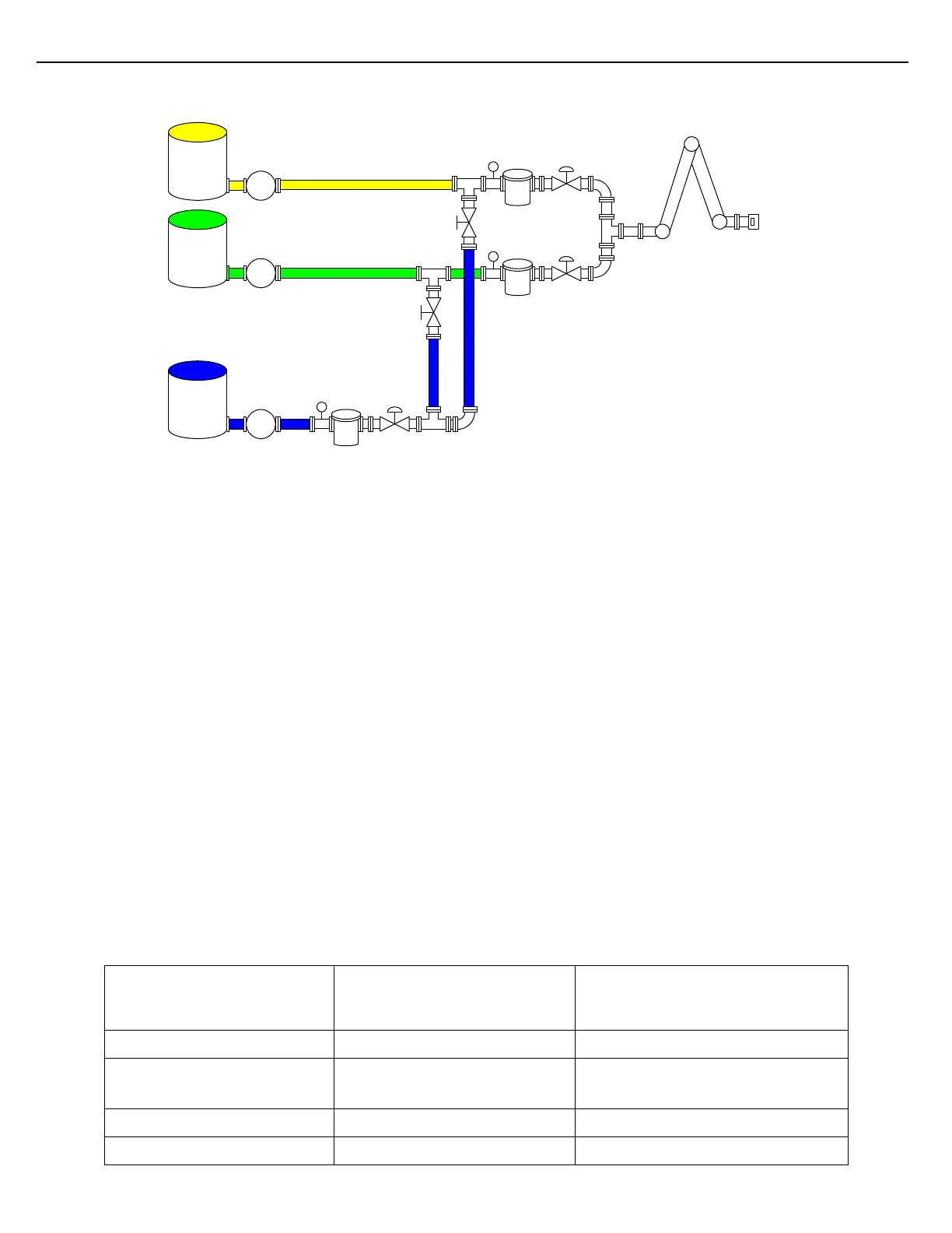
Figure 5.11 Ratio Blending with Side Stream Application
The example shows a single side-stream meter serving two primary components of a ratio blender. The side-
stream meter will only flow into one of the primary streams during a given batch. In the event that two primary
streams are used in a blend, the side-stream meter will still only flow into one of the primary streams.
At the preset-level, define the number of flow meters and components (liquids) that will be delivered through the
load arm. In this example there will be three flow meters and three components. Set the Blending Type
parameter found at the preset-level to RATIO.
At the meter-level configuration, default values can typically be used for the primary meters (Meter 1 & Meter 2).
When configuring parameters for Meter 3, enter a value in the Side-Stream On Mtr# parameter. By entering a
value of 1 for this parameter, Meter 3 is designated to be a side-stream of Meter 1. If it is necessary to flow
through more than one primary stream, also enable the parameter “Side-Stream on Any Meter” under Meter 3
configuration. This will allow the side-stream meter to flow into another primary stream if Meter 1 is not used in
the blend. The side-stream meter will always expect to flow through Meter 1 when Meter 1 is used in a blend, due
to the setting of the Side-Stream On Mtr# parameter.
It will probably be necessary to adjust the Dead Band rates of Meter 3, since the side-stream meter is typically
smaller than the primary stream meters. Reference the table for suggested settings. The Maximum Flow Rate
and Minimum Flow Rate parameters for Meter 3 will also need to be adjusted to match the flow meter
manufacturer’s specifications.
At the component-level configuration, the components are assigned to a particular meter, using the Meter#
parameter. Referencing the diagram in Figure 5.5, Component 1 is assigned to Meter 1, Component 2 is assigned
to Meter 2 and Component 3 is assigned to Meter 3.