Chapter 6 – Additive Control
Firmware Version 3/4.31.37
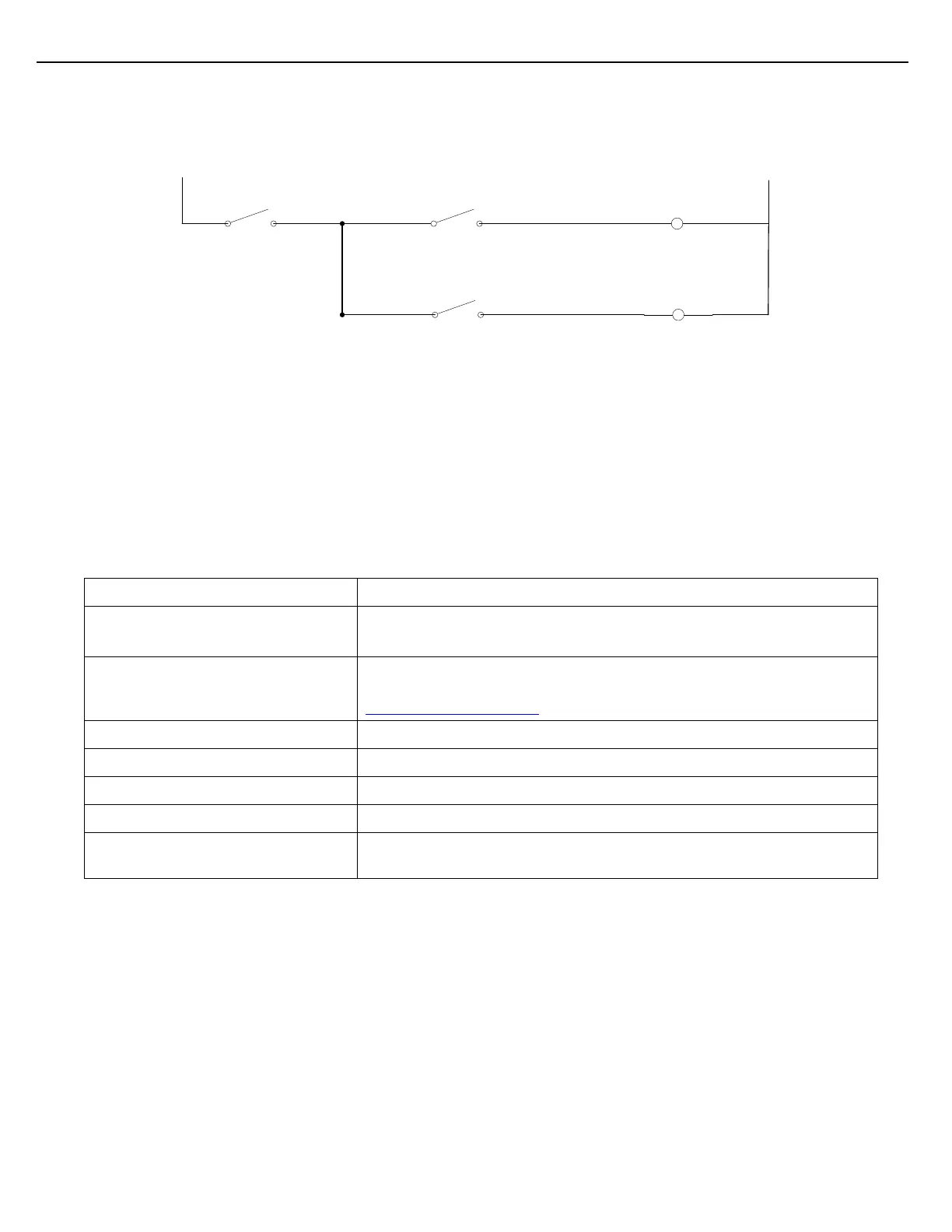
During a load, the selected Additive Block Valve output will be active at all times. The Additive Injection output
will periodically complete the circuit, energizing the Additive Block Valve solenoid, whenever an injection is
commanded.
L1
L2
Additive Injection
Output
Additive Block Valve
Output-Add #1
Additive Block Valve
Solenoid-Add #1
Additive Block Valve
Output-Add #2
Additive Block Valve
Solenoid-Add #2
Figure 6.6 Electrical Schematic using Block Valves as Injectors
6.5.11 CONFIGURING A COMMON METER WITH MULTIPLE ADDITIVES
This topic describes the minimum configuration needed to get an additive to operate using this method.
Configuration of the following parameters is mandatory. You can accomplish this using the I/O II Configuration
Tool or the I/O II keypad in Program mode. These parameters will have to be configured for each additive that is
assigned to the common injector.
Set this value to the FCM # where the additive is connected.
Set this value to zero for the internal I/O board.
Select the port that will serve as the Additive Injection Output. Note: A
corresponding additive input port will automatically be assigned. See the
Additive Port Assignment description above.
Additive Volume Per Injection
Enter the injection volume in appropriate units.
This parameter is not applicable.
Enter the additive meter’s K-factor in pulses per gallon.
Assign an output port that will provide an output to open an Additive
Block Valve. The Additive Block Valve will be used for additive selection.
The remaining parameters that apply to this additive method are optional. They are used to set up alarming,
pump outputs and permissive inputs. Some of the remaining parameters affect how the additive is delivered at
different stages of the load cycle. All Additive configuration screens and parameter descriptions are found in the
‘General Additive Setup’ section that follows. The “Parameters for Additive Methods” table lists the parameters
that apply to this method. Not all of the additive parameters are applicable to every additive delivery method. The
following table shows the parameters that apply to each of the four possible methods. “Yes” indicates that the
parameter applies to the additive method. “No” indicates that the parameter does not apply to the method.