70 - Maintenance Procedures
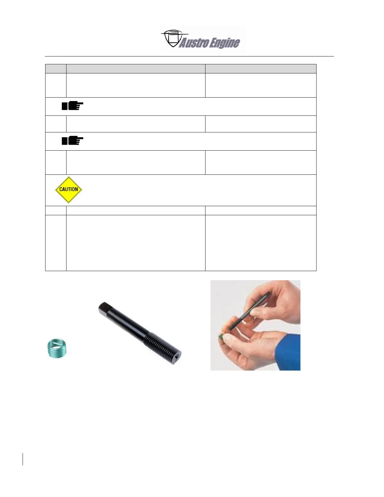
Turn the thread clockwise onto the insertion
mandrel until the spindle yoke engages the
tang.
Attach the large–sized components with clamps in an applicable holding
device (e.g. with protective jaws).
Put the insertion mandrel in vertical position on
the hole receiving the insert.
Carefully turn the spindle!
Turn the insert into the threaded hole until the
distance x between component surface and
threaded insert upper edge is reached.
The insert must not come out on the other side of the component.
Remove the insertion mandrel.
Remove the tang of the insert from the hole
with a tang breaker.
- Hit the end of the tang breaker with a
short heavy tap with a hammer. The
tang must break off the threaded
insert.
- Remove the tang from the hole.
Fig. 70 - 18 Insertion mandrel