EasyManua.ls Logo

Austro Engine E4 Series - Page 534

Default Icon
658 pages
Print Icon
To Next Page IconTo Next Page
To Previous Page IconTo Previous Page
Loading...
E4 Series
Maintenance Manual
Reciprocating
Engine
Page 246
E4.08.04
Rev. 29
85-Maintenance Procedures
01-Jul-2020
Detail Steps/Work Items
Key Items/References
Use a torque wrench to apply the torque values specified in the Table 85-1 at
the angle measuring gauge.
To complete the mechanical inspection do the following steps:
Turn the two-mass flywheel with a torque of 40 Nm in the counterclockwise (CCW)
direction.
Release and let it to come to the CCW end stop.
Turn the two-mass flywheel with a torque of 40 Nm in the clockwise (CW) direction.
Release and let it to come to the CW end stop.
Set the degree measuring gauge to zero.
Turn the two-mass flywheel with the specified torques (Refer to Table 85-1) in the CW
direction.
Do not set the degree measuring gauge to zero during the measurement
procedure.
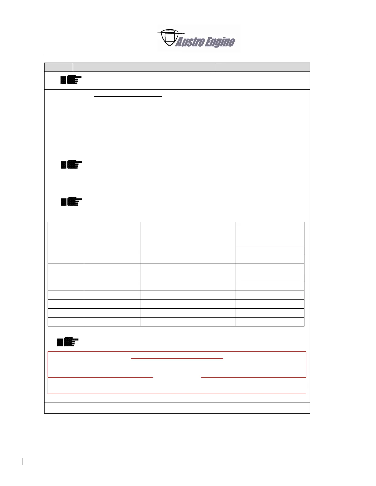
Record the clearance angle value on the degree measuring gauge in the table below.
The measured angle values must be within the minimum and maximum
tolerance values.
Torque
[Nm]
Minimum
tolerance [deg]
Measured value
Clockwise turning [deg]
Maximum tolerance
[deg]
25
2
12
50
2
18
75
7
23
100
13
29
125
18
34
150
24
40
175
29
45
200
34
50
300
41
57
Table 85-1
The tolerance values are mathematically rounded to make the measuring
process easier.
Mechanical Inspection performed:
FITTER
(Name, Date, Signature)
INSPECTOR
(Name, Date, Signature)
After the inspection is complete, remove the two-mass flywheel from the testing rig.

Table of Contents

Other manuals for Austro Engine E4 Series

Related product manuals