Platform Descriptions
Issue 8.0 July 2002
3-13
Except for power, all cabling entering the interconnection panel is connectorized
with the following industry standard connectors:
■ BNC connectors: The BNC connectors are used on all cables for
electrical low-speed interfaces.
■ D-subminiature connectors: The D-subminiature connectors are used
on all cables for the operation system and central office interfaces.
The power cables are connected to radio frequency (RF) filters on the
interconnection panel using push-on type connectors.
Low-Speed Shelf — System Controller Interconnect Panel —
ED6G999-32, G3 3
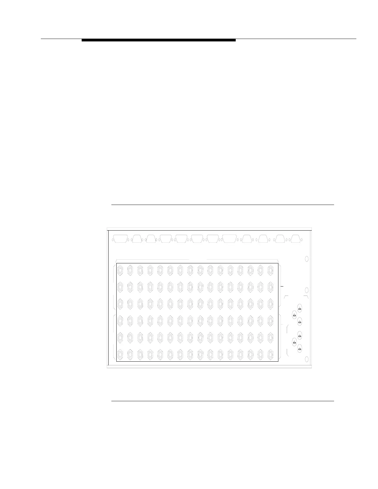
The new (G3) panel provides the same basic functionality as the older (G5) panel.
However, the placement of the power indicator LEDs has been rearranged. Also,
the CIT and User Panel connectors have been eliminated. Figure 3-6 shows the
G3 Interconnect Panel.
Figure 3-6. Interconnection Panel (Low-Speed Shelf —
System Controller) —ED6G999-32, G3
MISC DSCRT 2MISC DSCRT 1SER TLM 2SER TLM 1
2A/10A
LS INTFC
X.25
TIMING OUT 2TIMING OUT 1TIMING IN SECYTIMING IN PRIOFFICE ALMS
1A/9A
J125A
5B/13B5A/13A4B/12B4A/12A3B/11B3A/11A2B/10B1B/9B
J32A
J34A
J23AJ18AJ13AJ8A
J25AJ20AJ15AJ10A
1
2
1
2
3
3
1
2
1
2
3
3
1
2
1
2
3
3
1
2
1
2
3
3
1
2
1
2
3
3
In
Out
J3A
J5A
1
2
1
2
3
3
J156A P160A P164AP161A
J115A
J120A
J130A
6B/14B 7A/15A
J122A J127A J132A
1
2
1
2
3
3
1
2
1
2
3
3
1
2
1
2
3
3
J92A J86A J93AJ85A
J37A J42A J99A J104A
6A/14A
J117AJ106AJ101AJ44AJ39A
1
2
1
2
3
3
1
2
1
2
3
3
1
2
1
2
3
3
1
2
1
2
3
3
PAR T LM
P165A
P166A
1
2
1
2
3
3
CIT (DTE)
P158AP163A
J135A J140A
7B/15B 8A/16A
J137A J142A
1
2
1
2
3
3
1
2
1
2
3
3
-48V(B)
-48V
8B/16B
-48VR
PWR LN FLT
Out
In
-48(A)
PWR LN FLT
-48V
-48VR
adr04009.01eJK040997