Platform Descriptions
3-14 Issue 8.0 July 2002
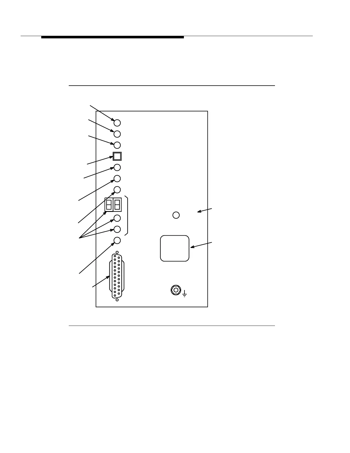
The user panel (Figure 3-7) provides −48 V power filters, a power on (PWR ON)
LED, an electrostatic discharge jack, and system level information. For more
information about the user panel, refer to Section 6, "Operations Interfaces."
Figure 3-7. User Panel (Enhanced) 6G999-31, G5
USE
CIT
Line
Locator
Use CIT
CIT
(DCE)
STRAP GROUND
W
CIT Connector
ACTY
LINE
LOCTR
Near-End
Activity
Far-End
Activity
NE
ACTY
FE
Abnormal
MN
ABN
ACO/
LOCTR
ESD WRIST
Pushbutton
PWR
ON
MJ
Minor Alarm
E
Identification
Label
CR
Critical Alarm
Major Alarm
Line Locator
Line
LINE
Alarm Cutoff/
NO. = 1W
-48 V Power On
LINE
NO. = 1E