Maintenance Description
Issue 8.0 July 2002
9-49
Optical Low Speed Protection Switching
Architecture 9
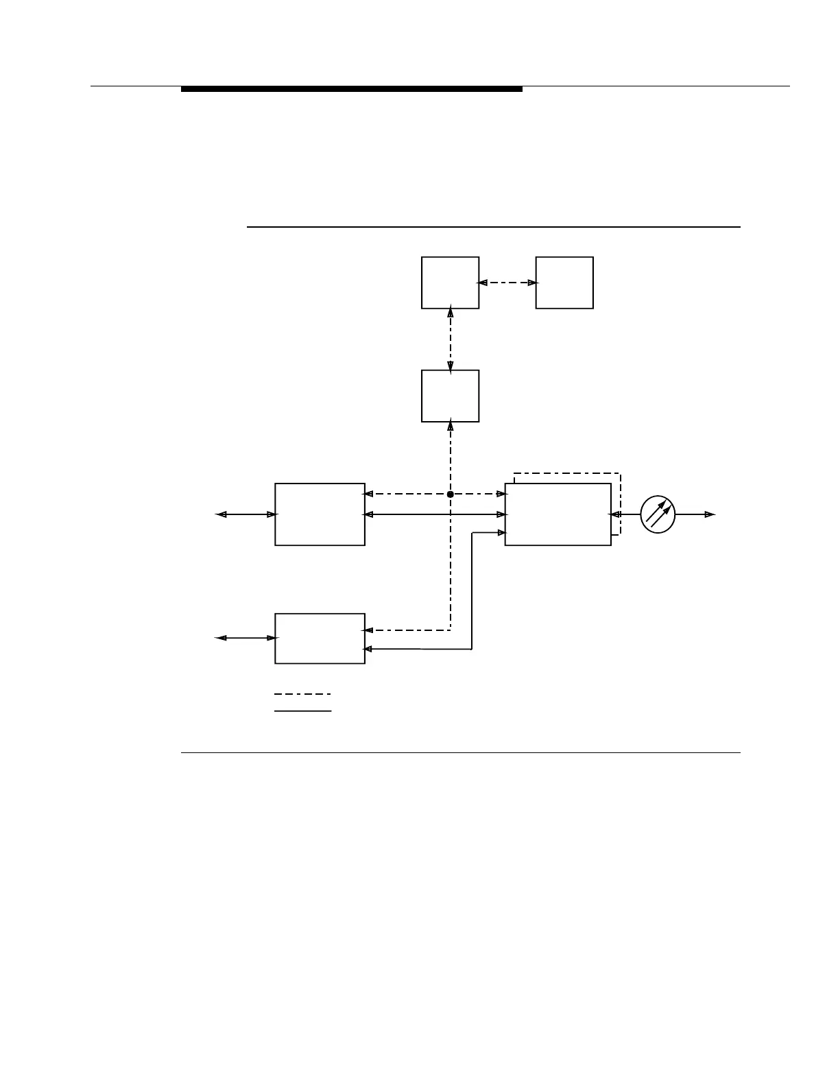
Figure 9-12 shows the optical low-speed protection switching architecture.
Figure 9-12. Optical Low Speed Protection Switching
Optical low-speed protection switching is only performed in the add (OC-3 to
OC-48) direction by an FT-2000 OC-48 Add/Drop-Rings Terminal. If the active
OC-3 line fails in the add (OC-3 to OC-48) direction, the board controller on the
OC3 (1.3 STD) circuit pack sends the information to the LNCTL circuit pack via
the BCLAN. If appropriate, the LNCTL circuit pack broadcasts a switch request to
the board controller on the OC48 TRMTR circuit pack. The board controller on the
OC48 TRMTR circuit pack activates the selector circuitry to choose the 155 Mb/s
signal from the standby OC3 (1.3 STD) circuit pack. The standby OC3 (1.3 STD)
circuit pack becomes the new active OC3 (1.3 STD) circuit pack.
Control
Transmission
Low Speed
1 OC-3
OC3
OC-48
SYSCTL
LNCTL
SYSMEM
LCLAN
BCLAN
Low Speed
OC48 TRMTR
OC48 RCVR
1 OC-3
OC3
Signal
Signal