Circuit Pack Descriptions
Issue 8.0 July 2002
7-45
General Description of Operation 7
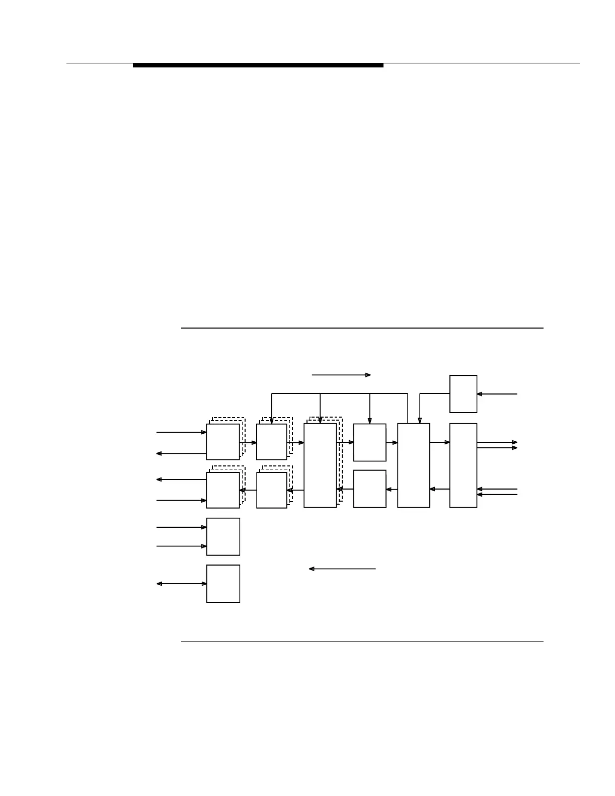
The STS1E circuit pack terminates three bidirectional EC-1 lines complying with
standard STSX-1 signal specifications. The three 51.84 Mb/s EC-1 signals are
multiplexed to one 155.52 Mb/s signal and sent to the OC48 Transmitter (OC48
TRMTR) circuit pack. In the receive direction, the STS1E circuit pack accepts one
155.52 Mb/s signal from an OC48 Receiver (OC48 RCVR) circuit pack and
demultiplexes it to three 51.84 Mb/s EC-1 signals. The STS1E circuit pack also
interfaces with the Line Controller (LNCTL) circuit pack for that particular OC-48
high speed line.
Detailed Description of Operation 7
Transmission Circuitry 7
Transmit Direction . 7Figure 7-16 provides an overall block diagram of the STS1E
circuit pack.
Figure 7-16. STS1E Circuit Pack Block Diagram
Line
Line
HS
(OUT)
From LSSW
Input
Protection
Intfc
Output
Protection
Intfc
Power
Circuit
Board
Controller
Circuit
Receiver
Driver
Receive Direction
Timing
Intfc
Intfc
TRMTRs
To OC48
From OC48
Transmit Direction
To LSSW (IN)
From TG3
(DS1)
BCLAN
-48V (B)
-48V (A)
RCVRs
From STSX-1
To STSX-1
Transmit
Receive
Byte
Processor
System Clock
STS-3
Byte
Processor
Transmit
Pointer
Processor
Recieve
Pointer
Processor