Technical Specifications
10-6 Issue 8.0 July 2002
For detailed circuit pack information and software compatibility, refer to Table 7-1 and the
circuit pack descriptions in Section 7, "Circuit Pack Descriptions."
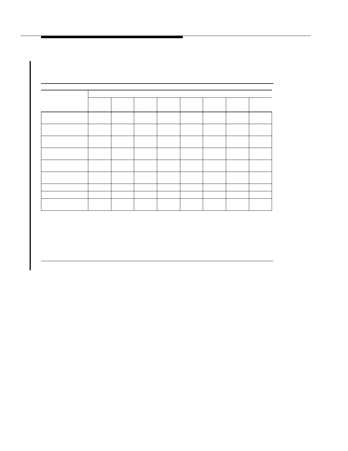
Table 10-2. OC-48 Loss Budget Specifications for 739E/G[1-8] OC48 TRMTR Circuit Packs
Parameter
OC48 Transmitter Circuit Pack Code and Wavelength (in nm)
739E1/G1
1549.32
739E2/G2
1550.92
739E3/G3
1552.52
739E4/G4
1554.13
739E5/G5
1555.75
739E6/G6
1557.37
739E7/G7
1558.98
739E8/G8
1560.61
Maximum Transmitter
Power (P
Tmax
)
*
* Transmit and receive powers are referenced to points S and R as shown in Figure 10-1.
−3.3 dBm −4.6 dBm −5.8 dBm −6.5 dBm −7.0 dBm −7.5 dBm −7.3 dBm −5.8 dBm
Minimum Transmitter
Power (P
Tmin
)
†
† These values include transmitter/receiver connectors @ 0.7 dB each (worst case) and the system margins.
−6.2 dBm −7.5 dBm −8.7 dBm −9.4 dBm −9.9 dBm −10.4 dBm −10.2 dBm −8.7 dBm
Maximum Received
Power (P
Rmax
)
‡
‡ The receiver sensitivity and maximum received power values are measured at a BER of 1x10
-10
.
−11.0 dBm −11.0 dBm −11.0 dBm −11.0 dBm −11.0 dBm −11.0 dBm −11.0 dBm −11.0 dBm
Receiver Sensitivity
(P
Rmin
)
†‡
−27.0 dBm −27.0 dBm −27.0 dBm − 27.0 dBm −27.0 dBm −27.0 dBm −27.0 dBm −27.0 dBm
MinimumSystemGain
(S-R)
20.8 dB 19.5 dB 18.3 dB 17.6 dB 17.1 dB 16.6 dB 16.8 dB 18.3 dB
Optical Path Penalty
Penalty (P
O
)
2dB 2dB 2dB 2dB 2dB 2dB 2dB 2dB
Maximum Loss Budget 20.3 dB 19.0 dB 17.8 dB 17.1 dB 16.6 dB 16.1 dB 16.3 dB 17.8 dB
Minimum Loss Budget
§
§ These values assume that the maximum received power limitations are not exceeded.
10.0 dB 10.0 dB 10.0 dB 10.0 dB 10.0 dB 10.0 dB 10.0 dB 10.0 dB
Typical Maximum
Distance
¶
¶ These distances are based on an assumption of 0.25 dB/km loss, including fiber loss and splice loss.
81.2 km 76 km 71.2 km 68.4 km 66.4 km 64.4 km 65.2 km 71.2 km