Maintenance Description
Issue 8.0 July 2002
9-35
2-Fiber Ring Protection Switching Example 9
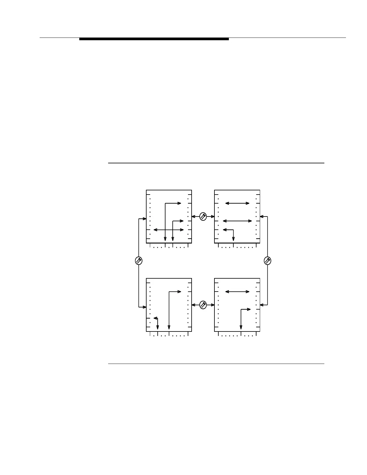
Figure 9-6 shows an example of a 2-fiber bidirectional, line-switched ring with four
nodes during normal transmission. (STS-3 tributaries 1 through 8 are service
STS-3 tributaries and STS-3 tributaries 9 through 16 are protection tributaries.)
Service STS-3 tributary 6 is used to carry service traffic between low-speed
interface slot 4A at node 0 and low-speed interface slot 5A at node 2. Service
STS-3 tributary 3 is used to carry service traffic between low-speed interface slot
3A at node 1 and low-speed interface slot 2A at node 3. Protection STS-3 tributary
14 is used to carry extra traffic between low-speed interface slot 2B at node 0 and
low-speed interface slot 4B at node 3. For more information about
cross-connections at FT-2000 OC-48 Add/Drop-Rings Terminals, refer to
Volume I, Section 8, "Administration and Provisioning."
Figure 9-6. Bidirectional Line-Switched 2-Fiber Ring (Normal
Transmission)
Figure 9-7 shows a 2-fiber bidirectional, line-switched ring when a fiber cut occurs
between two nodes. Automatic 2-fiber ring protection switching occurs in
response to a signal fail or signal degrade condition on an incoming OC-48
high-speed signal.
Node 0
1W 1E
1A 2B 8B
1
OC-48
5A
14
1
6
Node 1
1W 1E
1A 8B
14
1
14
1
66
Node 3
1E 1W
1A 8B
1
OC-48
14
1
Node 2
1E 1W
1A 8B
14
1
14
1
6
OC-48OC-48
4A
16
16 16 16
16 16 16 16
3 3 3
3
3A
2A 4B