Circuit Pack Descriptions
Issue 8.0 July 2002
7-53
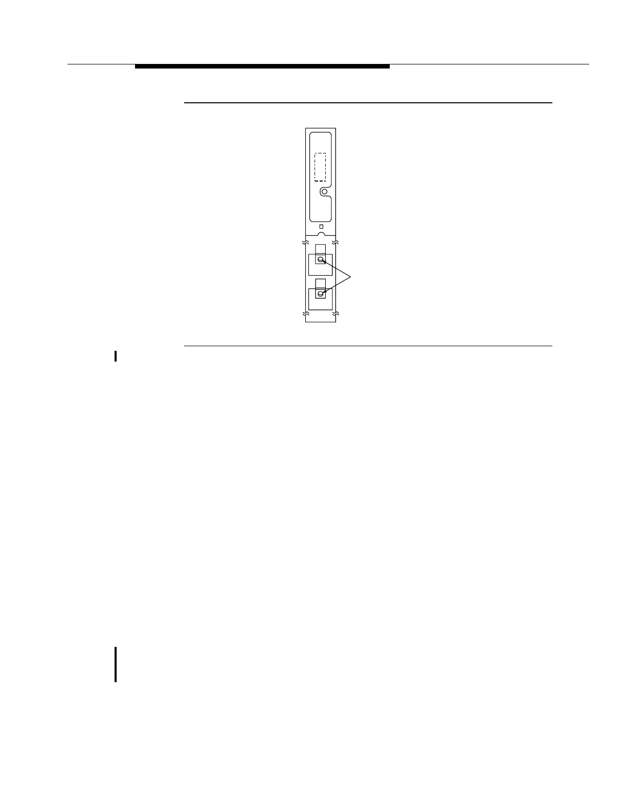
Figure 7-17. OC3 (1.3 STD) (LAA10/LAA10B) Circuit Pack
General Description of Operation 7
The OC3 (1.3 STD) circuit pack terminates one bidirectional OC-3 line. In the
transmit direction (toward the OC-48 line), the OC3 (1.3 STD) circuit pack
converts the incoming OC-3 optical signal to an electrical STS-3/3c signal (155.52
Mb/s). The STS-3/3c signal is demultiplexed into three STS-1 signals (51.84
Mb/s) and synchronized to the system clock. The three STS-1 signals are then
multiplexed back to one STS-3/3c signal and sent to an OC48 Transmitter (OC48
TRMTR) circuit pack. In the receive direction (toward the OC-3 line), the OC3 (1.3
STD) circuit pack accepts one STS-3/3c signal from an OC48 Receiver (OC48
RCVR) circuit pack and demultiplexes it to three STS-1 signals. The three STS-1
signals are synchronized to the system clock, multiplexed back to one STS-3/3c
signal, and converted to an optical OC-3 signal for transmission. The OC3 (1.3
STD) circuit pack also interfaces with the Line Controller (LNCTL) circuit pack for
that particular OC-48 high speed line.
Detailed Description of Operation 7
Transmission Circuitry 7
Transmit Direction. 7Figure 7-18 provides an overall block diagram of the OC3 (1.3
STD) LAA10 circuit pack. Figure 7-19 shows an overall block diagram of the OC3
(1.3 STD) LAA10B circuit pack. To take advantage of the additional capabilities of
the LAA10B circuit pack, you must be running Release 9.0 or later software.
FAULT
xxxxxxxxx_
Optical
Connector
OUT
IN
LAA10
OC3