Control, Transmission, and Synchronization Interfaces
Issue 8.0 July 2002
5-13
Through Timed Mode 5
In the through timed mode, an intermediate site (FT-2000 OC-48 Add/Drop-Rings
Terminal or FT-2000 OC-48 Repeater Bay) derives timing from the incoming
OC-48 signals.
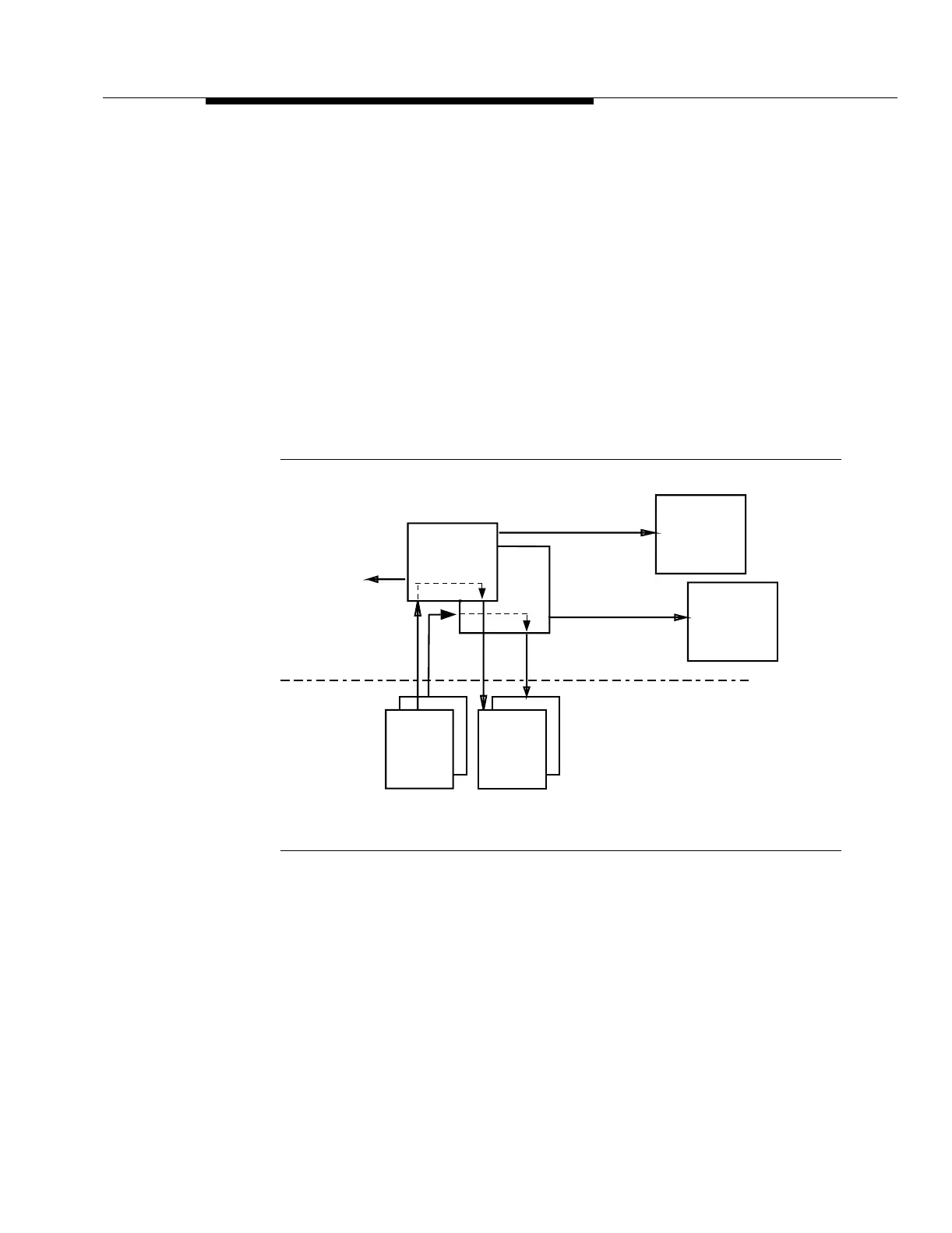
In the FT-2000 OC-48 Add/Drop-Rings Terminal, the TG3 (DS1) circuit packs
derive timing from the incoming OC-48 signals (Figure 5-6). The TG3 (DS1) circuit
packs accept an OC-48 line reference signal (25.92 MHz) from the OC48 RCVR
circuit packs and derive the internal synchronization used by the transmission
circuit packs. For example, the TG3 (DS1) circuit pack that accepts the OC-48 line
reference signal from high speed line 1E derives timing for the OC-48 signal
transmitted on high speed line 1W. Also, the TG3 (DS1) circuit pack that accepts
the OC-48 line reference signal from high speed line 1W derives timing for the
OC-48 signal transmitted on high speed line 1E.
Figure 5-6. Through Timed Synchronization (FT-2000 OC-48
Add/Drop-Rings Terminal)
The OC-48 line reference signals are continuously monitored. If the primary
OC-48 line reference signal becomes corrupted, the TG3 (DS1) circuit pack will
select the secondary OC-48 line reference signal without causing service
degradations. If the primary and secondary OC-48 line reference signals fail, the
digital phase-locked loop (DPLL) circuit holds the on-board oscillator frequency at
the last good reference sample while the references are repaired (holdover
mode). This mechanism is provided so that operation with or without an external
BITS clock can be easily accommodated. In the holdover mode, the on-board
oscillator frequency will not degrade below the stratum 3 level.
TG3-2
155.52 MHz
System Controller
TRMTR
1W
1E
155.52 MHz
OC48
Low Speed
Interfaces
Low Speed Shelf -
DS1 Outputs
1E
1W
RCVR
25.92 MHz
OC48
Condensed/Enhanced
High Speed Shelf
(or High Speed Shelf)
TG3-1
Low Speed
Interfaces
155.52 MHz