Maintenance Description
9-50 Issue 8.0 July 2002
In the drop (OC-48 to OC-3) direction, the OC48 RCVR circuit pack routes the
same 155 Mb/s signal to the active and standby OC3 (1.3 STD) circuit packs.
Optical Low Speed Protection Switching
Example 9
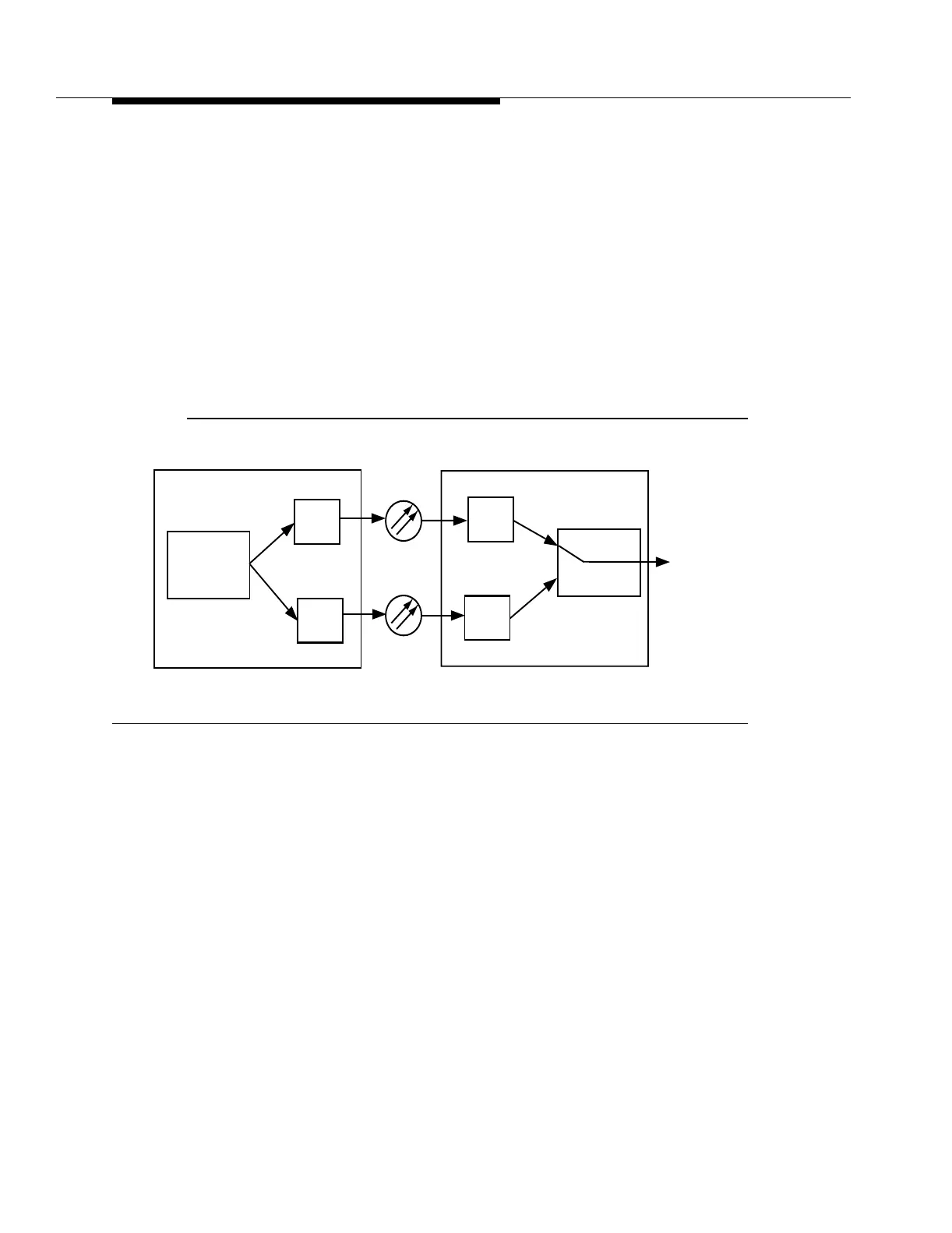
Figure 9-13 shows two OC-3 lines (only one direction of transmission is shown)
and two FT-2000 OC-48 Add/Drop-Rings Terminals. The FT-2000 OC-48
Add/Drop-Rings Terminal at Office A transmits service traffic on both OC-3 lines.
The FT-2000 OC-48 Add/Drop-Rings Terminal at Office B monitors the two OC-3
lines independently and chooses one OC-3 line as the active line and the other
OC-3 line as the standby line.
Figure 9-13. 1+1 OC-3 Line (Normal Transmission)
Figure 9-14 shows two OC-3 lines (only one direction of transmission is shown)
and two FT-2000 OC-48 Add/Drop-Rings Terminals when a fiber cut occurs on the
active OC-3 line. Automatic 1+1 OC-3 line protection switching occurs in response
to a signal fail or signal degrade condition on the incoming OC-3 signal.
Optical low-speed protection switching is only performed in the add (OC-3 to
OC-48) direction by the FT-2000 OC-48 Add/Drop-Rings Terminal at Office B. The
board controller on the OC48 TRMTR circuit pack activates the selector circuitry
to choose the 155 Mb/s or 622 Mb/s signal from the standby OC3 (1.3 STD) or
OC12 (1.3 STD) circuit pack. The standby OC3 (1.3 STD) circuit pack becomes
the new active OC3 (1.3 STD) circuit pack. The original active OC-3 line becomes
the standby OC-3 line.
OC-3
Standby
Active
OC3
Office A
Office B
OC48 TRMTR
OC3
OC3
OC48 RCVR
OC3