Control, Transmission, and Synchronization Interfaces
Issue 8.0 July 2002
5-9
FT-2000 OC-48 Repeater Bay 5
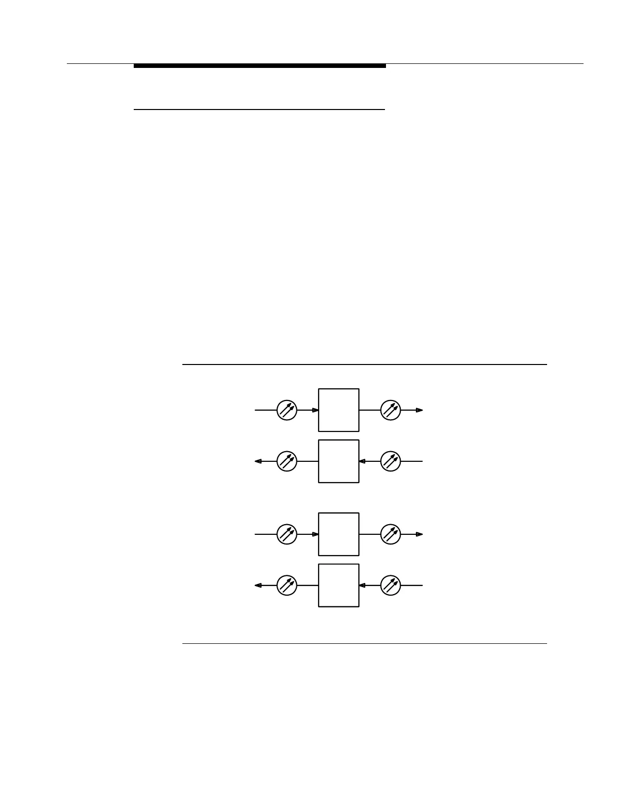
The FT-2000 OC-48 Repeater Bay regenerates optical OC-48 signals for up to six
OC-48 high speed lines. Figure 5-4 shows a transmission block diagram of the
FT-2000 OC-48 Repeater Bay for one 1x1 system.
Two OC48 Regenerator (OC48 REGENR) circuit packs make a repeater. One
OC48 REGENR circuit pack receives an incoming OC-48 signal from high speed
line 1W, for example, and transmits it toward high speed line 1E. The other OC48
REGENR circuit pack receives an incoming OC-48 signal from high speed line 1E
and transmits it toward high speed line 1W.
Internally, the FT-2000 OC-48 Repeater Bay employs standard synchronous
multiplexing. (Refer to Appendix A, "A SONET Overview.") For example, the
incoming optical OC-48 signal from high speed line 1W is converted to an
electrical STS-48 signal and demultiplexed to sixteen 155 Mb/s signals. This
allows certain SONET section overhead bytes to be extracted, monitored, and
controlled. The 155 Mb/s signals are then multiplexed to one STS-48 signal, and
the SONET section overhead bytes are inserted. The STS-48 signal is then
converted back to an optical OC-48 signal for transmission on high speed line 1E.
Figure 5-4. FT-2000 OC-48 Repeater Bay Transmission
Block Diagram
PW
REGENR
REGENR
OC48
OC48
OC-48
OC-48
OC-48
OC-48
PE
REGENR
REGENR
1E1W
OC48
OC48
OC-48
OC-48
OC-48
OC-48