Maintenance Description
9-44 Issue 8.0 July 2002
One dedicated protection DS3 circuit pack
*
provides protection for the service
DS3 circuit packs, and one dedicated protection STS1E circuit pack* provides
protection for the service STS1E circuit packs. However, only one protection
low-speed interface circuit pack (DS3 or STS1E) can be switched into service at a
time. Two Low Speed Switch (LSSW) circuit packs are used to perform low-speed
protection switching.*
Table 9-5 shows the standard protection switching priorities in descending order
of priority used by the FT-2000 OC-48 Add/Drop-Rings Terminal.
Each Low Speed Shelf can be equipped with one protection DS3 and/or one
protection STS1E circuit pack. However, only one service DS3 or STS1E circuit
pack can be protected at a time.
Each service low-speed interface circuit pack (DS3 or STS1E) can be assigned a
high or low protection priority. This allows a high priority circuit pack to preempt
any previous switch to protection by a lower priority circuit pack. Switch requests
of equal priority will be met in the order in which they are received. If two requests
occur simultaneously, the one with the lower slot address will take priority.
Figure 9-11 shows the low-speed protection switching architecture.
* The protection DS3 and STS1E circuit packs may be placed in the P1 or P2 slot of the Low
Speed Shelf - System Controller.
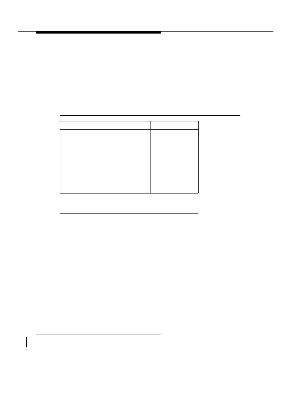
Table 9-5. Electrical low Speed Protection Switching Priorities
Switch Priority (Descending Order) Source of Request
Reset* CIT/OS
Protection hardware failure Automatic
Lockout of protection CIT/OS
Lockout of service CIT/OS
Forced switch CIT/OS
Circuit pack failure/removal Automatic
Manual switch CIT/OS
Wait to restore Automatic
* Resetting the low-speed switch priority
(FAULT-Switch-Low Speed-Priority:Reset) has no effect
on any automatic switch priority except wait to restore.